|
数据搜索系统,热门电子元器件搜索 |
|
|
数据搜索系统,热门电子元器件搜索 |
|
RFEVAL3-R1 数据表(PDF) 19 Page - rfsolutions.ltd |
|
|
|||||||||||||||||||||||||||||
RFEVAL3-R1 数据表(HTML) 19 Page - rfsolutions.ltd |
|
|
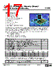
19 / 24 page  RF / IR Encoder / Decoder Chipset RF600E RF Evaluation Boards, RF600D HiRK decoder area. AM-HiRK-433 receiver/decoder module. (M5) Learn switch. (SW2) Learn LED. (LED7) Data LED’s. (LED8, 9, 10) Power supply area. 5 volt regulator. (U5) Supply indicator (LED11) The radio keyfob is a standard R. F. Solutions AM-110C3-433 keyfob which contains an RF600E encoder chip and also an AM radio transmitter circuit. Three push buttons allow the user to send commands to the RFEVAL2 board where the signals will be received and decoded. The RFEVAL2 board is supplied with a circuit diagram and also a parts list and can be used for a wide range of development tasks including the following. Remote switching - software and hardware systems can be simply prototyped and tested. Range and environment testing - these initial stages of project design can be carried out and valuable results obtained without the expense of PCB design and procurement. Solve the great AM/FM question - the low cost of AM modules must be balanced with their lower performance when compared to FM and accurate comparisons of performance can be carried out with this board. Aerial test - the transmitter board has provision for both AM and FM modules and can be fitted with helical stub and 1/4 wave whip aerials, thus allowing module and aerial performance to be tested and optimised. RF Input Circuit. The RF input stage of the RFEVAL2 board can be implemented using either a radio receiver module or alternately using the composite hybrid receiver / decoder HiRK module. The can accept up to 3 radio modules and each module has an associated pair of option links. One of these couples the +5 volt supply to the module and the other allows for the connection of the ‘data out’ signal to the decoder IC. The need for a +5 volt option link may not be immediately apparent but most radio receivers are in practice transmitters as well and radiate from their local oscillator stage. If these signals are picked up by a nearby receiver then they may well cause distortion of incoming ‘real’ signals or in extreme cases my completely prevent operation of the receiver. The four modules which may be fitted to the board are as follows. FM-RRFQ1 FM module (M3) which receives signals from a compatible FM transmitter module such as the FM-RTFQ1. Operation is possible at data rates up to 4.8Kbps and at distances up to 250 metres over open ground. AM-HRR3 AM module (M4) which receives signals from a compatible AM transmitter module such as the AM-RT4 or AM-RT5. These modules will operate at up to 4 Kbps and over a range of up to 500 metres. The super-regenerative circuit used, results in a low cost device with adequate performance for many short range applications. Note that this module position will accept RRS3 modules which utilise a superhet circuit to give improved performance and range over the HRR3 devices. Irrespective of how many modules are fitted, it will be necessary to connect the +5 volt and data lines of one module using the link options filed on the PCB. It is important that only one pair of links be made at DS600-9 Sept ‘04 ©2004 Reg. No. 227 4001, ENGLAND Page 19 |
|
|
链接网址 |
| ALLDATASHEET是否为您带来帮助? [ DONATE ] |
关于 Alldatasheet | 广告服务 | 联系我们 | 隐私政策 | 数据表链接 | 链接交换 | 制造商名单 All Rights Reserved©Alldatasheet.com |
| Russian : Alldatasheetru.com | Korean : Alldatasheet.co.kr | Spanish : Alldatasheet.es | French : Alldatasheet.fr | Italian : Alldatasheetit.com Portuguese : Alldatasheetpt.com | Polish : Alldatasheet.pl | Vietnamese : Alldatasheet.vn Indian : Alldatasheet.in | Mexican : Alldatasheet.com.mx | British : Alldatasheet.co.uk | New Zealand : Alldatasheet.co.nz |
|
Family Site : ic2ic.com |
icmetro.com |
 Chinese ▼
 English
 Chinese
 German
 Japanese
 Russian
 Korean
 Spanish
 French
 Italian
 Portuguese
 Polish
 Vietnamese
 Indian
 Mexican
 British
 New Zealand