|
数据搜索系统,热门电子元器件搜索 |
|
|
数据搜索系统,热门电子元器件搜索 |
|
RFEVAL3-R1 数据表(PDF) 22 Page - rfsolutions.ltd |
|
|
|||||||||||||||||||||||||||||
RFEVAL3-R1 数据表(HTML) 22 Page - rfsolutions.ltd |
|
|
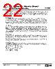
22 / 24 page  RF / IR Encoder / Decoder Chipset RF600E RF Evaluation Boards, RF600D Infra Red Input Circuit. The Infra Red (IR) input stage consists solely of the IS436 IR detector device. This part is constructed in a 3 pin package with integral lens and acts as a detector and demodulator with Schmitt trigger data slicer. If an IR encoder is activated and pointed at the detector then the output waveform will be of +ve mark and can be coupled to the RF600D subsystem by setting the input selector OPT1, to IR and the mark selector OPT3, to FM. Serial Data Output Circuit. The RF600D subsystem produces a serial data output at logic level which can be fed into another microcontroller or alternately it may be desirable to pass the data into a device which will accept RS232 level data. The serial data output circuit area consists of a MAX232A TTL – RS232 level converter (U4) which converts the logic level serial data output from the RF600D into an RS232 level data stream. The data is output on the 9 way ‘D’ connector (J1) with data on pin 2 and ground reference on pin 5. Note that the DSR line (pin 6 on J1) is held at RS232 high level and may be used to enable the receiving device. HiRK Decoder Circuit. The HiRK decoder system offers the designer a ‘single component’ solution to AM data reception and decoding. In many ways the features and operation of the decoder system are almost identical to those offered by the radio-module-plus-RF600D system described above. Indeed, operation of the learn switch (LEARN-2) and associated LED7 are identical to those of the RF600D subsystem.. The 3 data outputs on the HiRK module are connected to LED 8, 9 and 10 and these show the states of data inputs S0 – S2 on the encoder RF600E chip. For a full description of the function and application of this module please see datasheet DS097. Power Supply Circuit. The power supply for the board allows the use of an on-board PP3 battery plugged into connector J10. Alternately an 8 – 12 volt dc power source may be connected to J1 or a standard R. F. Solutions power supply (as used with ‘ICEPIC’ product) may be plugged into socket J5. Note that only one power source should be connected at any one time. The dc input supply is regulated by the 78L08, 5 volt regulator (U5) and a power on indicator (LED11) is provided to show the presence of the 5 volt supply. KeeLoq Parameters. The RF600D and RF600E devices utilise The Microchip KeeLoq coding system to guarantee secure transfer of the data between the encoder and the decoder. The coding parameters which are applied to the KeeLoq structure is as follows: Modulation format: Manchester coded Baud rate: 400 us, short time out Manufacturers code: R. F. Solutions. Long Guard Time: Enabled. Auto Shut Off Timer: Enabled. DS600-9 Sept ‘04 ©2004 Reg. No. 227 4001, ENGLAND Page 22 |
|
|
链接网址 |
| ALLDATASHEET是否为您带来帮助? [ DONATE ] |
关于 Alldatasheet | 广告服务 | 联系我们 | 隐私政策 | 数据表链接 | 链接交换 | 制造商名单 All Rights Reserved©Alldatasheet.com |
| Russian : Alldatasheetru.com | Korean : Alldatasheet.co.kr | Spanish : Alldatasheet.es | French : Alldatasheet.fr | Italian : Alldatasheetit.com Portuguese : Alldatasheetpt.com | Polish : Alldatasheet.pl | Vietnamese : Alldatasheet.vn Indian : Alldatasheet.in | Mexican : Alldatasheet.com.mx | British : Alldatasheet.co.uk | New Zealand : Alldatasheet.co.nz |
|
Family Site : ic2ic.com |
icmetro.com |
 Chinese ▼
 English
 Chinese
 German
 Japanese
 Russian
 Korean
 Spanish
 French
 Italian
 Portuguese
 Polish
 Vietnamese
 Indian
 Mexican
 British
 New Zealand