|
数据搜索系统,热门电子元器件搜索 |
|
|
数据搜索系统,热门电子元器件搜索 |
|
K3HB-R 数据表(PDF) 12 Page - Omron Electronics LLC |
|
|
|||||||||||||||||||||||||||||
K3HB-R 数据表(HTML) 12 Page - Omron Electronics LLC |
|
|
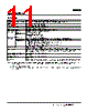
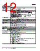
12 / 32 page  12 Timer Interval Indicator K3HB-P ■ Characteristics Display range −19,999 to 99,999 Measurement accuracy (at 23±5 °C) ±0.08% rgd ±1 digit (for voltage pulse/open collector sensors) Measurement range Functions F1, F3, and F4:10 ms to 3,200 s Function F2: 20 ms to 3,200 s Functions F5 and F6: 0 to 4 gigacounts Input signals • No-voltage contact (30 Hz max. with ON/OFF pulse width of 15 ms min.) •Voltage pulse •Opencollector Connectable sensors ON residual voltage: 3 V max. OFF leakage current: 1.5 mA max. Load current: Must have a switching capacity of 20 mA or higher. Must be able to properly switch load currents of 5 mA or less. Comparative output response time (transistor output) 2 ms max. (time until the comparative output is made when there is a forced sudden change in the input signal from 15% to 95% or 95% to 15%) Linear output response time 10 ms max. (time until the final analog output value is reached when there is a forced sudden change in the input signal from 15% to 95% or 95% to 15%) Insulation resistance 20 M Ω min. (at 500 VDC) Dielectric strength 2,300 VAC for 1 min between external terminals and case Noise immunity 100 to 240 VAC models: ±1,500 V at power supply terminals in normal or common mode (waveform with 1-ns rising edge and pulse width of 1 µs/100 ns) 24 VAC/VDC models: ±1,500 V at power supply terminals in normal or common mode (waveform with 1-ns rising edge and pulse width of 1 µs/100 ns) Vibration resistance Frequency: 10 to 55 Hz; Acceleration: 50 m/s2, 10 sweeps of 5 min each in X, Y, and Z directions Shock resistance 150 m/s2 (100 m/s2 for relay outputs) 3 times each in 3 axes, 6 directions Weight Approx. 300 g (Base Unit only) Degree of protection Front panel Conforms to NEMA 4X for indoor use (equivalent to IP66) Rear case IP20 Terminals IP00 + finger protection (VDE0106/100) Memory protection EEPROM (non-volatile memory) Number of rewrites: 100,000 Applicable standards UL61010C-1, CSA C22.2 No. 1010.1 (evaluated by UL) EN61010-1 (IEC61010-1): Pollution degree 2/Overvoltage category II EN61326: 1997, A1: 1998, A2: 2001 EMC EMI: EN61326+A1 industrial applications Electromagnetic radiation interference CISPR 11 Group 1, Class A: CISPRL16-1/-2 Terminal interference voltage CISPR 11 Group 1, Class A: CISPRL16-1/-2 EMS: EN61326+A1 industrial applications Electrostatic Discharge Immunity EN61000-4-2: 4 kV (contact), 8 kV (in air) Radiated Electromagnetic Field Immunity EN61000-4-3: 10 V/m 1 kHz sine wave amplitude modulation (80 MHz to 1 GHz, 1.4GHz to 2 GHz) Electrical Fast Transient/Burst Immunity EN61000-4-4: 2 kV (power line), 1 kV (I/O signal line) Surge Immunity EN61000-4-5: 1 kV with line (power line), 2 kV with ground (power line) Conducted Disturbance Immunity EN61000-4-6: 3 V (0.15 to 80 MHz) Power Frequency Magnetic Immunity EN61000-4-8: 30 A/m (50 Hz) continuous time Voltage Dips and Interruptions Immunity EN61000-4-11: 0.5 cycle, 0 °/180°, 100% (rated voltage) Mode Input frequency range ON/OFF pulse width ON voltage OFF voltage Input impedance F1 to F4 0 to 50 kHz 9 µs min. 4.5 to 30 V −30 to 2 V 10 k Ω F5, F6 0 to 30 kHz 16 µs min. Mode Input frequency range ON/OFF pulse width Note: The Digital Time Interval Meter will malfunction if a pulse greater than the input frequency range is input. SYSERR may appear on the display. F1 to F4 0 to 50 kHz 9 µs min. F5, F6 0 to 30 kHz 16 µs min. |
|
链接网址 |
| ALLDATASHEET是否为您带来帮助? [ DONATE ] |
关于 Alldatasheet | 广告服务 | 联系我们 | 隐私政策 | 数据表链接 | 链接交换 | 制造商名单 All Rights Reserved©Alldatasheet.com |
| Russian : Alldatasheetru.com | Korean : Alldatasheet.co.kr | Spanish : Alldatasheet.es | French : Alldatasheet.fr | Italian : Alldatasheetit.com Portuguese : Alldatasheetpt.com | Polish : Alldatasheet.pl | Vietnamese : Alldatasheet.vn Indian : Alldatasheet.in | Mexican : Alldatasheet.com.mx | British : Alldatasheet.co.uk | New Zealand : Alldatasheet.co.nz |
|
Family Site : ic2ic.com |
icmetro.com |
 Chinese ▼
 English
 Chinese
 German
 Japanese
 Russian
 Korean
 Spanish
 French
 Italian
 Portuguese
 Polish
 Vietnamese
 Indian
 Mexican
 British
 New Zealand