|
数据搜索系统,热门电子元器件搜索 |
|
|
数据搜索系统,热门电子元器件搜索 |
|
ADA4661-2ARMZ-R7 数据表(PDF) 23 Page - Analog Devices |
|
|
|||||||||||||||||||||||||||||
ADA4661-2ARMZ-R7 数据表(HTML) 23 Page - Analog Devices |
|
|
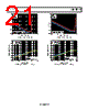
23 / 32 page  Data Sheet ADA4661-2 Rev. 0 | Page 23 of 32 system voltages with proprietary protection circuitry. This regu- lation circuitry protects the input devices from the high supply voltages at which the amplifier can operate. The input devices are also protected from large differential input voltages by clamp diodes (D1 and D2). These diodes are buffered from the inputs with two 120 Ω resistors (R1 and R2). The diodes conduct significant current whenever the differen- tial voltage exceeds approximately 600 mV; in this condition, the differential input resistance falls to 240 Ω. It is possible for a significant amount of current to flow through these protection diodes. The user must ensure that current flowing into the input pins is limited to the absolute maximum of 10 mA. GAIN STAGE The second stage of the amplifier is composed of an NPN differential pair (Q1, Q2) and folded-cascode transistors (M13 to M20). The amplifier features nested Miller compensation (C1 to C3). OUTPUT STAGE The ADA4661-2 features a complementary output stage consisting of the M21 and M22 transistors. These transistors are configured in a Class AB topology and are biased by the voltage source, V1. This topology allows the output voltage to go within millivolts of the supply rails, achieving a rail-to-rail output swing. The output voltage is limited by the output impedance of the transis- tors, which are low RON MOS devices. The output voltage swing is a function of the load current and can be estimated using the output voltage to supply rail vs. load current graphs (see Figure 20, Figure 23, Figure 24, and Figure 27). The high voltage and high current capability of the ADA4661-2 output stage requires the user to ensure that it operates within the thermal safe operating area (see the Maximum Power Dissipation section). MAXIMUM POWER DISSIPATION The ADA4661-2 is capable of driving an output current up to 220 mA. However, the usable output load current drive is limited to the maximum power dissipation allowed by the device package. The absolute maximum junction temperature for the ADA4661-2 is 150°C (see Table 5). The junction temperature can be estimated as follows: TJ = PD × θJA + TA The power dissipated in the package (PD) is the sum of the quiescent power dissipation and the power dissipated by the output stage transistor. It can be calculated as follows: PD = (VSY × ISY) + (VSY − VOUT) × ILOAD where: VSY is the power supply rail. ISY is the quiescent current. VOUT is the output of the amplifier. ILOAD is the output load. Do not exceed the maximum junction temperature for the device, 150°C. Exceeding the junction temperature limit can cause degradation in the parametric performance or even destroy the device. To ensure proper operation, it is necessary to observe the maximum power derating curves. Figure 71 shows the maximum safe power dissipation in the package vs. the ambient temperature on a standard 4-layer JEDEC board. The exposed pad of the LFCSP package is soldered to the board. Figure 71. Maximum Power Dissipation vs. Ambient Temperature Refer to Technical Article MS-2251, Data Sheet Intricacies— Absolute Maximum Ratings and Thermal Resistances, for more information. RAIL-TO-RAIL INPUT AND OUTPUT The ADA4661-2 features rail-to-rail input and output with a supply voltage from 3 V to 18 V. Figure 72 shows the input and output waveforms of the ADA4661-2 configured as a unity-gain buffer with a supply voltage of ±9 V. With an input voltage of ±9 V, the ADA4661-2 allows the output to swing very close to both rails. Additionally, it does not exhibit phase reversal. Figure 72. Rail-to-Rail Input and Output 0 0.2 0.4 0.6 0.8 1.0 1.2 1.4 1.6 0 25 50 75 100 125 150 AMBIENT TEMPERATURE (°C) 8-LEAD LFCSP θJA =83.5°C/W 8-LEAD MSOP θJA =142°C/W TJMAX =150°C TIME (200µs/DIV) –10 –8 –6 –4 –2 0 2 4 8 6 10 VIN VOUT VSY = ±9V VIN = ±9V AV = 1 RL = 10kΩ CL = 10pF |
|
链接网址 |
| ALLDATASHEET是否为您带来帮助? [ DONATE ] |
关于 Alldatasheet | 广告服务 | 联系我们 | 隐私政策 | 数据表链接 | 链接交换 | 制造商名单 All Rights Reserved©Alldatasheet.com |
| Russian : Alldatasheetru.com | Korean : Alldatasheet.co.kr | Spanish : Alldatasheet.es | French : Alldatasheet.fr | Italian : Alldatasheetit.com Portuguese : Alldatasheetpt.com | Polish : Alldatasheet.pl | Vietnamese : Alldatasheet.vn Indian : Alldatasheet.in | Mexican : Alldatasheet.com.mx | British : Alldatasheet.co.uk | New Zealand : Alldatasheet.co.nz |
|
Family Site : ic2ic.com |
icmetro.com |
 Chinese ▼
 English
 Chinese
 German
 Japanese
 Russian
 Korean
 Spanish
 French
 Italian
 Portuguese
 Polish
 Vietnamese
 Indian
 Mexican
 British
 New Zealand