|
数据搜索系统,热门电子元器件搜索 |
|
|
数据搜索系统,热门电子元器件搜索 |
|
LMX2430 数据表(PDF) 32 Page - National Semiconductor (TI) |
|
|
|
|||||||||||||||||||||||||||||
LMX2430 数据表(HTML) 32 Page - National Semiconductor (TI) |
|
|
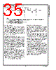
32 / 49 page  LMX243x FinRF Input Impedance Test Setup 20053591 The block diagram above illustrates the setup required to measure the LMX243x device’s RF input impedance. The same setup is used for the LMX2430TM Evaluation Board. Measuring the device’s input impedance facilitates the de- sign of appropriate matching networks to match the PLL to the VCO, or in more critical situations, to the characteristic impedance of the printed circuit board (PCB) trace, to pre- vent undesired transmission line effects. The FinIF input impedance is evaluated in the same way. Before the actual measurements are taken, the Network Analyzer needs to be calibrated, i.e. the error coefficients need to be calculated. The Network Analyzer’s calibration standard is used to calculate these coefficients. The calibra- tion standard includes an open, short and a matched load. A 1-port calibration is implemented here. To calculate the coefficients, the PLL chip is first removed from the PCB. A piece of semi-rigid coaxial cable is then soldered to the pad on the PCB which is equivalent to the FinRF pin on the PLL chip. Proper grounding near the ex- posed tip of the semi-rigid coaxial cable is required for accurate results. Note that the DC blocking capacitor is removed for this test. The Network Analyzer port is then connected to the other end of the semi-rigid coaxial cable. In this way, the semi-rigid coaxial cable acts as a transmission line. This transmission line adds electrical length and pro- duces an offset from the reference plane of the Network Analyzer; therefore, it must be included in the calibration. The desired operating frequency is then set. The typical frequency range selected for the LMX243x device’s RF syn- thesizer is from 100 MHz to 6000 MHz. The Network Analyzer calculates the calibration coefficients based on the measured S 11 parameters. With this all done, calibration is now complete. The PLL chip is then placed on the PCB. A power supply is then connected to Vcc. The EN, ENosc, and OSCin pins are all tied to Vcc. Alternatively, the OSCin pin can be tied to ground. In this setup, the complementary input (FinRF*)is AC coupled to ground. With the Network Analyzer still con- nected to the semi-rigid coaxial cable, the measured FinRF impedance is displayed. The OSCin input impedance is measured in the same way. The impedance is measured when the oscillator buffer is powered up (ENosc is set HIGH) and when the oscillator buffer is powered down (ENosc pin is set LOW). www.national.com 32 |
|
链接网址 |
| ALLDATASHEET是否为您带来帮助? [ DONATE ] |
关于 Alldatasheet | 广告服务 | 联系我们 | 隐私政策 | 数据表链接 | 链接交换 | 制造商名单 All Rights Reserved©Alldatasheet.com |
| Russian : Alldatasheetru.com | Korean : Alldatasheet.co.kr | Spanish : Alldatasheet.es | French : Alldatasheet.fr | Italian : Alldatasheetit.com Portuguese : Alldatasheetpt.com | Polish : Alldatasheet.pl | Vietnamese : Alldatasheet.vn Indian : Alldatasheet.in | Mexican : Alldatasheet.com.mx | British : Alldatasheet.co.uk | New Zealand : Alldatasheet.co.nz |
|
Family Site : ic2ic.com |
icmetro.com |
 Chinese ▼
 English
 Chinese
 German
 Japanese
 Russian
 Korean
 Spanish
 French
 Italian
 Portuguese
 Polish
 Vietnamese
 Indian
 Mexican
 British
 New Zealand