|
数据搜索系统,热门电子元器件搜索 |
|
|
数据搜索系统,热门电子元器件搜索 |
|
LMX2430 数据表(PDF) 42 Page - National Semiconductor (TI) |
|
|
|
|||||||||||||||||||||||||||||
LMX2430 数据表(HTML) 42 Page - National Semiconductor (TI) |
|
|
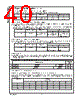
42 / 49 page  2.0 Programming Description (Continued) 2.5.4 RF_PD - RF Synthesizer Powerdown (R1[23]) The RF_PD bit is used to switch the RF PLL between a powered up and powered down mode. Furthermore, the RF_PD bit operates in conjuction with the RF_CPT bit to set a synchronous or an asynchronous powerdown mode. Refer to Section 2.4.4 for more details on how to program the RF_CPT bit. Control Bit Register Location Description Function 01 RF_PD R1[23] RF Powerdown RF PLL Active RF PLL Powerdown 2.6 R2 REGISTER The R2 Register contains the RF_TOC control word. The RF_TOC is used to setup the RF syhnthesizer’s Fastlock circuitry. The RF_TOC is a 12-bit binary counter programmable from 0 to 4095. Reg 23 22 21 20 19 18 17 16 15 14 13 12 11 10 9876543210 DATA[20:0] FIELD ADDRESS [2:0] FIELD R2 000000000 RF_TOC[11:0] 0 1 0 2.6.1 RF_TOC[0:11] - RF Synthesizer Timeout Counter (R2[14:3]) The FLoutRF pin can be configured as a general purpose CMOS TRI-STATE output or as a Fastlock output by programming the RF_TOC appropriately. When the RF_TOC is programmed from 0 to 3, Automatic Fastlock is disabled, and the FLoutRF pin is either configured as a general purpose CMOS TRI-STATE output or Manual Fastlock is enabled. When the RF_TOC is programmed to 0, the FLoutRF pin will be in TRI-STATE (high impedance) mode. The charge pump current is then the value specified by RF_CPG (R0[19]). When the RF_TOC is programmed to 1, the FLoutRF pin is pulled to a LOW state. The charge pump current is then set to a HIGH gain state (RF_CPG bit = 1). This condition is known as the Manual Fastlock. When the RF_TOC is programmed to 2, the FLout_RF pin will again be pulled to a LOW state, but this time the charge pump current is the value specified by RF_CPG (R0[19]). When the RF_TOC is programmed to 3, the FLoutRF pin is pulled to a HIGH state. Again, the charge pump current is the value specified by RF_CPG (R0[19]). When the RF_TOC is programmed from 4 to 4095, Fastlock is enabled and the FLoutRF pin is pulled to a LOW state. Fastlock will time-out after the specified number of PFD events. At this time, the FLoutRF pin will switch to TRI-STATE (high impedance) mode. The value programmed into RF_TOC represents the number of PFD events that the RF synthesizer will spend in the Fastlock state. Note that any write to the RF_TOC requires a PFD event on the RF synthesizer to latch the contents. This means that writes to the RF_TOC take effect synchronously with the next PFD event. RF_TOC[11:0] FastLock Mode Fastlock Period [PFD Events] FLoutRF Pin Functionality/ State I CPoutRF Magnitude 0 Disabled N/A General Purpose. High Impedance State I CPoutRF magnitude controlled by R0[19] 1 Enabled Manual Fastlock N/A General Purpose. Logic LOW State I CPoutRF =4 mA 2 Disabled N/A General Purpose. Logic LOW State I CPoutRF magnitude controlled by R0[19] 3 Disabled N/A General Purpose. Logic HIGH State I CPoutRF magnitude controlled by R0[19] 4 Enabled Automatic Fastlock 4 FastLock. Logic LOW State. Switches to High Impedance after 4 PFD events I CPoutRF =4 mA Switches to 1 mA after 4 PFD events … ……… … 4095 Enabled Automatic Fastlock 4095 FastLock. Logic LOW State. Switches to High Impedance after 4095 PFD events I CPoutRF =4 mA Switches to 1 mA after 4095 PFD events www.national.com 42 |
|
链接网址 |
| ALLDATASHEET是否为您带来帮助? [ DONATE ] |
关于 Alldatasheet | 广告服务 | 联系我们 | 隐私政策 | 数据表链接 | 链接交换 | 制造商名单 All Rights Reserved©Alldatasheet.com |
| Russian : Alldatasheetru.com | Korean : Alldatasheet.co.kr | Spanish : Alldatasheet.es | French : Alldatasheet.fr | Italian : Alldatasheetit.com Portuguese : Alldatasheetpt.com | Polish : Alldatasheet.pl | Vietnamese : Alldatasheet.vn Indian : Alldatasheet.in | Mexican : Alldatasheet.com.mx | British : Alldatasheet.co.uk | New Zealand : Alldatasheet.co.nz |
|
Family Site : ic2ic.com |
icmetro.com |
 Chinese ▼
 English
 Chinese
 German
 Japanese
 Russian
 Korean
 Spanish
 French
 Italian
 Portuguese
 Polish
 Vietnamese
 Indian
 Mexican
 British
 New Zealand