|
数据搜索系统,热门电子元器件搜索 |
|
|
数据搜索系统,热门电子元器件搜索 |
|
AD8067ART-R2 数据表(PDF) 20 Page - Analog Devices |
|
|
|||||||||||||||||||||||||||||
AD8067ART-R2 数据表(HTML) 20 Page - Analog Devices |
|
|
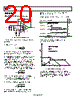
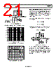
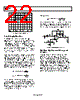
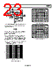
20 / 24 page  AD8067 Rev. 0 | Page 20 of 24 APPLICATIONS Wideband Photodiode Preamp – + VOUT VB CF + CS CD CM CM RF AD8067 RSH = 1011Ω CS IPHOTO CF RF Figure 49. Wideband Photodiode Preamp Figure 49 shows an I/V converter with an electrical model of a photodiode. The basic transfer function is: F F F PHOTO OUT R sC R I V + × = 1 where I PHOTO is the output current of the photodiode, and the parallel combination of R F and CF sets the signal bandwidth. The stable bandwidth attainable with this preamp is a function of R F, the gain bandwidth product of the amplifier, and the total capacitance at the amplifier’s summing junction, including C S and the amplifier input capacitance. R F and the total capacitance produce a pole in the amplifier’s loop transmission that can result in peaking and instability. Adding C F creates a zero in the loop transmission that compensates for the pole’s effect and reduces the signal bandwidth. It can be shown that the signal bandwidth resulting in a 45° phase margin (f(45)) is defined by the expression: () S F 45 C R π GBP f × × = 2 GBP is the unit gain bandwidth product, R F is the feedback resistance, and C S is the total capacitance at the amplifier summing junction (amplifier + photodiode + board parasitics). The value of C F that produces f (45) can be shown to be: GBP R π C C F S F × × = 2 The frequency response in this case will show about 2 dB of peaking and 15% overshoot. Doubling C F and cutting the bandwidth in half will result in a flat frequency response, with about 5% transient overshoot. The preamp’s output noise over frequency is shown in Figure 50. Contributor Expression RMS Noise (µV)1 RF × 2 57 1 2 4 2 . × × × × f R kT F 152 Amp to f1 1 f Vnoise × 4.3 Amp (f2–f1) ( ) 1 2 2 f – f C C C C C V F D F M S noise × + + + × 96 Amp (Past f2) ( ) 57 1 3 2 . × × + + + × f C C C C C V F D F M S noise 684 RSS Total 708 Table 2. RMS Noise Contributions of Photodiode Preamp 1 RMS noise with RF = 50 kΩ, CS = 0.67 pF, CF = 0.33 pF, CM = 1.5 pF, and CD = 2.5 pF. FREQUENCY – Hz RF NOISE f1 NOISE DUE TO AMPLIFIER VEN f2 1 2πRF(CF + CS + CM + 2C D) f1 = f2 = 1 2πRFCF f3 = GBP (CS + CM + 2C D + CF)/CF VEN (C F + CS + CM + 2C D)/CF f3 Figure 50. Photodiode Voltage Noise Contributions Figure 51 shows the AD8067 configured as a transimpedance photodiode amplifier. The amplifier is used in conjunction with a JDS Uniphase photodiode detector. This amplifier has a bandwidth of 9.6 MHz as shown in Figure 52 and is verified by the design equations shown in Figure 50. |
|
|
链接网址 |
| ALLDATASHEET是否为您带来帮助? [ DONATE ] |
关于 Alldatasheet | 广告服务 | 联系我们 | 隐私政策 | 数据表链接 | 链接交换 | 制造商名单 All Rights Reserved©Alldatasheet.com |
| Russian : Alldatasheetru.com | Korean : Alldatasheet.co.kr | Spanish : Alldatasheet.es | French : Alldatasheet.fr | Italian : Alldatasheetit.com Portuguese : Alldatasheetpt.com | Polish : Alldatasheet.pl | Vietnamese : Alldatasheet.vn Indian : Alldatasheet.in | Mexican : Alldatasheet.com.mx | British : Alldatasheet.co.uk | New Zealand : Alldatasheet.co.nz |
|
Family Site : ic2ic.com |
icmetro.com |
 Chinese ▼
 English
 Chinese
 German
 Japanese
 Russian
 Korean
 Spanish
 French
 Italian
 Portuguese
 Polish
 Vietnamese
 Indian
 Mexican
 British
 New Zealand