|
数据搜索系统,热门电子元器件搜索 |
|
|
数据搜索系统,热门电子元器件搜索 |
|
ENICSF2811PBKA 数据表(PDF) 103 Page - Texas Instruments |
|
|
|||||||||||||||||||||||||||||
ENICSF2811PBKA 数据表(HTML) 103 Page - Texas Instruments |
|
|
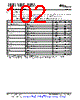
103 / 172 page  TMS320F2810, TMS320F2811, TMS320F2812 TMS320C2810, TMS320C2811, TMS320C2812 www.ti.com SPRS174T – APRIL 2001 – REVISED MAY 2012 6.14 Clock Requirements and Characteristics 6.14.1 Input Clock Requirements The clock provided at the XCLKIN pin generates the internal CPU clock cycle. Table 6-6. Input Clock Frequency PARAMETER MIN TYP MAX UNIT Resonator 20 35 Crystal 20 35 fx Input clock frequency MHz Without PLL 4 150 XCLKIN With PLL 5 100 fl Limp mode clock frequency 2 MHz Table 6-7. XCLKIN Timing Requirements – PLL Bypassed or Enabled NO. MIN MAX UNIT C8 tc(CI) Cycle time, XCLKIN 6.67 250 ns C9 tf(CI) Fall time, XCLKIN 6 ns C10 tr(CI) Rise time, XCLKIN 6 ns C11 tw(CIL) Pulse duration, X1/XCLKIN low as a percentage of tc(CI) 40 60 % C12 tw(CIH) Pulse duration, X1/XCLKIN high as a percentage of tc(CI) 40 60 % Table 6-8. XCLKIN Timing Requirements – PLL Disabled NO. MIN MAX UNIT C8 tc(CI) Cycle time, XCLKIN 6.67 250 ns C9 tf(CI) Fall time, XCLKIN Up to 30 MHz 6 ns 30 MHz to 150 MHz 2 C10 tr(CI) Rise time, XCLKIN Up to 30 MHz 6 ns 30 MHz to 150 MHz 2 C11 tw(CIL) Pulse duration, X1/XCLKIN low as a percentage of tc(CI) XCLKIN ≤ 120 MHz 40 60 % 120 < XCLKIN ≤ 150 MHz 45 55 C12 tw(CIH) Pulse duration, X1/XCLKIN high as a percentage of tc(CI) XCLKIN ≤ 120 MHz 40 60 % 120 < XCLKIN ≤ 150 MHz 45 55 Table 6-9. Possible PLL Configuration Modes PLL MODE REMARKS SYSCLKOUT Invoked by tying XPLLDIS pin low upon reset. PLL block is completely disabled. PLL Disabled Clock input to the CPU (CLKIN) is directly derived from the clock signal present at XCLKIN the X1/XCLKIN pin. Default PLL configuration upon power-up, if PLL is not disabled. The PLL itself is PLL Bypassed bypassed. However, the /2 module in the PLL block divides the clock input at the XCLKIN/2 X1/XCLKIN pin by two before feeding it to the CPU. Achieved by writing a non-zero value “n” into PLLCR register. The /2 module in the PLL Enabled (XCLKIN * n) / 2 PLL block now divides the output of the PLL by two before feeding it to the CPU. Copyright © 2001–2012, Texas Instruments Incorporated Electrical Specifications 103 Submit Documentation Feedback Product Folder Link(s): TMS320F2810 TMS320F2811 TMS320F2812 TMS320C2810 TMS320C2811 TMS320C2812 |
|
链接网址 |
| ALLDATASHEET是否为您带来帮助? [ DONATE ] |
关于 Alldatasheet | 广告服务 | 联系我们 | 隐私政策 | 数据表链接 | 链接交换 | 制造商名单 All Rights Reserved©Alldatasheet.com |
| Russian : Alldatasheetru.com | Korean : Alldatasheet.co.kr | Spanish : Alldatasheet.es | French : Alldatasheet.fr | Italian : Alldatasheetit.com Portuguese : Alldatasheetpt.com | Polish : Alldatasheet.pl | Vietnamese : Alldatasheet.vn Indian : Alldatasheet.in | Mexican : Alldatasheet.com.mx | British : Alldatasheet.co.uk | New Zealand : Alldatasheet.co.nz |
|
Family Site : ic2ic.com |
icmetro.com |
 Chinese ▼
 English
 Chinese
 German
 Japanese
 Russian
 Korean
 Spanish
 French
 Italian
 Portuguese
 Polish
 Vietnamese
 Indian
 Mexican
 British
 New Zealand