|
数据搜索系统,热门电子元器件搜索 |
|
|
数据搜索系统,热门电子元器件搜索 |
|
ADRF6520ACPZ-R7 数据表(PDF) 19 Page - Analog Devices |
|
|
|||||||||||||||||||||||||||||
ADRF6520ACPZ-R7 数据表(HTML) 19 Page - Analog Devices |
|
|
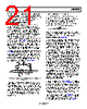
19 / 29 page  Data Sheet ADRF6520 Rev. 0 | Page 19 of 29 THEORY OF OPERATION 36MHz TO 720MHz PROGRAMMABLE FILTERS 30dB VVA BASEBAND INPUTS BASEBAND OUTPUTS FILTER, CHIP ENABLE, AND DC OFFSET LOOP PROGRAMMING SPI BUS ANALOG GAIN CONTROL 30mV/dB 6dB SPI INTERFACE 30dB VVA 18dB 12dB 18dB Figure 65. Signal Path Block Diagram for a Single Channel of the ADRF6520 The ADRF6520 consists of a matched pair of input VGAs followed by programmable filters, 6 dB fixed gain amplifiers, and finally another matched pair of variable gain amplifiers and output ADC drivers. The filters can be bypassed and powered down through the SPI interface for operation beyond the maximum filter bandwidth. The block diagram of a single channel is shown in Figure 65. The programmability of the filter bandwidth through the SPI offers great flexibility when coping with signals in the presence of noise and large, undesired signals near the desired band. The entire differential signal chain is dc-coupled. The bandwidth and gain setting controls for the two channels are shared, ensuring close matching of their magnitude and phase responses. The ADRF6520 can be fully disabled through the ENBL pin or the enable bit in the SPI register. Filtering and amplification are fundamental operations in any signal processing system. Filtering is necessary to select the intended signal while rejecting out of band noise and interferers. Amplification increases the level of the desired signal to overcome noise added by the system. When used together, filtering and amplification can extract a low level signal of interest in the presence of noise and out of band interferers. Such analog signal processing alleviates the requirements on the analog, mixed signal, and digital components that follow. INPUT VGAs The input VGAs are designed to have low noise and high linearity. The VGAs have a differential input impedance of 100 Ω, maximum gain of 18 dB, and minimum gain of −12 dB, providing a 30 dB gain range. They are designed to drive the filters with up to 1.5 V p-p of undesired signal or 0.75 V p-p of desired signal, or a combination of both. The input to the ADRF6520 must be ac-coupled. The topology of the input VGA is such that its noise figure (NF) degrades dB for dB as its gain is reduced, although its high linearity is maintained across its full input range. The input VGA can drive up to 3 V p-p at its output; however, it is recommended that the VGA be kept to the aforementioned limits to avoid overdriving the filter or 6 dB fixed gain amplifier. RMS DETECTOR To measure the signal level at the critical interface of the VGA1 output and the programmable filter input, an rms detector was implemented. The rms detector simultaneously measures both channels at the VGA1 output and reports the sum of the two at the VRMS pin. On-chip averaging capacitors set the minimum settling time for the VRMS voltage to roughly 50 ns for most of the signal measurement range. The on-chip capacitors can be augmented by placing capacitors between the CFLT1 and CFLT2 pins and VPS. Off-chip capacitors are needed in most cases to obtain an accurate rms measurement of the input signal, as well as to reduce the modulation ripple in the VRMS output voltage. The rms detector responds in a linear in volts manner, with the VRMS voltage representing the rms value of the input signal with the following relationship at maximum VGA1 gain: VRMS = k × [RMS(ch1 input) + RMS(ch2 input)] where RMS(x) is the root mean square value, and it is assumed that sufficiently large filtering capacitors are chosen to allow averaging of the modulation content. The previous relationship applies at maximum VGA1 gain only. When VGA1 gain is reduced, the VRMS output voltage also decreases proportionately. Relating VRMS, the gain of VGA1 and the summation of the rms values of the channel inputs is VRMS = 1(V/VRMS)(VGA1 Linear Voltage Gain)(RMS(ch1 input) + RMS(ch2 input)) For example, if VGA1 is at its maximum gain of 18 dB, the equation reduces down to VRMS = 8(V/VRMS)(RMS(ch1 input) + RMS(ch2 input)) And at the VGA1 minimum gain of −12 dB, the equation reduces down to VRMS = 0.25(V/VRMS) × (RMS(ch1 input) + RMS(ch2 input)) |
|
|
链接网址 |
| ALLDATASHEET是否为您带来帮助? [ DONATE ] |
关于 Alldatasheet | 广告服务 | 联系我们 | 隐私政策 | 数据表链接 | 链接交换 | 制造商名单 All Rights Reserved©Alldatasheet.com |
| Russian : Alldatasheetru.com | Korean : Alldatasheet.co.kr | Spanish : Alldatasheet.es | French : Alldatasheet.fr | Italian : Alldatasheetit.com Portuguese : Alldatasheetpt.com | Polish : Alldatasheet.pl | Vietnamese : Alldatasheet.vn Indian : Alldatasheet.in | Mexican : Alldatasheet.com.mx | British : Alldatasheet.co.uk | New Zealand : Alldatasheet.co.nz |
|
Family Site : ic2ic.com |
icmetro.com |
 Chinese ▼
 English
 Chinese
 German
 Japanese
 Russian
 Korean
 Spanish
 French
 Italian
 Portuguese
 Polish
 Vietnamese
 Indian
 Mexican
 British
 New Zealand