|
数据搜索系统,热门电子元器件搜索 |
|
|
数据搜索系统,热门电子元器件搜索 |
|
ADAR2004ACCZ-R7 数据表(PDF) 22 Page - Analog Devices |
|
|
|||||||||||||||||||||||||||||
ADAR2004ACCZ-R7 数据表(HTML) 22 Page - Analog Devices |
|
|
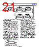
22 / 37 page  ADAR2004 Data Sheet Rev. 0 | Page 22 of 37 PARALLEL CHIP CONTROL Up to 16 devices (a total of 64 channels) can be driven by a single set of four state machine control lines, three common SPI lines, and a CS line for each chip. Using this method, the total number of digital control lines is 7 + N, where N is the number of ADAR2004 ICs (see Figure 45 for a basic diagram). Parallel chip control can be used to minimize the total number of digital control lines. The SPI lines can be reduced to two common lines if 3-wire mode is selected by setting the SDOACTIVE and SDOACTIVE_ bits (Register 0x000, Bit 4 and Bit 3, respectively) low. If 3-wire SPI mode is used, the total number of digital lines is 6 + N. SEQUENCERS ADAR2004 (1) COMMON SEQUENCER LINES COMMON SPI LINES SPI CS LINES SPI SEQUENCERS ADAR2004 (2) SPI SEQUENCERS ADAR2004 (16) SPI Figure 45. SPI and State Machine Digital Lines For Addressing and Controlling Up to 16 ADAR2004 Devices MULTICHIP FREQUENCY SWEEP Figure 46 shows an example of how the two state machines can be used to complete a multichip frequency sweep from 10 GHz to 16 GHz (that is, receive on all four channels on a single chip while at a fixed frequency range, move to the next chip and receive on all channels, moving through 16 chips in total, and then move to the next frequency and repeat the process). This example assumes that the state machine control lines are connected in parallel for up to 16 devices (64 channels, see Figure 45). Initially, pulses on RxRST and MRST put both state machines in State 0, which in this case, is a sleep mode. Next, pulses on MADV and RxADV advance both state machines to their first active state (receiving on all channels of ADAR2004 IC 1). After ADAR2004 IC 1 receives the signal, an additional pulse on RxADV activates all channels on ADAR2004 IC 2 while putting the multiplier/filter of the first chip into a ready mode and the receivers of that chip into a sleep mode to prevent disrupting the multiplier/filter signal before the receiver turns off. This sequence continues until all 16 ADAR2004 devices receive at the first frequency or range. At that point, a pulse is applied to both MADV and RxADV to advance the multiplier/filter to the next frequency range of interest and set the ADAR2004 IC 1 back into an active mode. Another series of RxADV pulses follow until ADAR2004 IC 16 is receiving the new frequency range. Table 8 describes how the receiver state machine for each ADAR2004 can be set up to work in sequence. Each device is turned fully on for only one state, but these states are all offset from each other. To run this sequence, where up to 16 devices are swept with all state machines driven in parallel, 16 receive states are used inside the loop, with the sleep state (State 0) used as a reset condition. If there were more tiles of 16 chips in the array that need to receive after the tile described in Table 8, this tile can have a reset pulse sent to put the sequencers into the initial sleep mode to wait for their turn to receive again. |
|
链接网址 |
| ALLDATASHEET是否为您带来帮助? [ DONATE ] |
关于 Alldatasheet | 广告服务 | 联系我们 | 隐私政策 | 数据表链接 | 链接交换 | 制造商名单 All Rights Reserved©Alldatasheet.com |
| Russian : Alldatasheetru.com | Korean : Alldatasheet.co.kr | Spanish : Alldatasheet.es | French : Alldatasheet.fr | Italian : Alldatasheetit.com Portuguese : Alldatasheetpt.com | Polish : Alldatasheet.pl | Vietnamese : Alldatasheet.vn Indian : Alldatasheet.in | Mexican : Alldatasheet.com.mx | British : Alldatasheet.co.uk | New Zealand : Alldatasheet.co.nz |
|
Family Site : ic2ic.com |
icmetro.com |
 Chinese ▼
 English
 Chinese
 German
 Japanese
 Russian
 Korean
 Spanish
 French
 Italian
 Portuguese
 Polish
 Vietnamese
 Indian
 Mexican
 British
 New Zealand