|
数据搜索系统,热门电子元器件搜索 |
|
|
数据搜索系统,热门电子元器件搜索 |
|
LTC4373CMS8 数据表(PDF) 14 Page - Analog Devices |
|
|
|||||||||||||||||||||||||||||
LTC4373CMS8 数据表(HTML) 14 Page - Analog Devices |
|
|
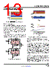
14 / 20 page  LTC4372/LTC4373 14 Rev. 0 For more information www.analog.com APPLICATIONS INFORMATION Using the LTC4372’s SHDN and 2UPU When SHDN goes high, the LTC4372 enters shutdown and asserts a 1mA pull-down between GATE and SOURCE to turn off the external MOSFET. It also turns off most of the internal circuitry, reducing IIN to 0.5μA. GATE is held low with a 3μA pull-down to GND. If IN and SOURCE are connected together, IQ = 3.0μA + 0.5μA = 3.5μA. Shutting down the part does not interrupt forward current flow as a path is still present through M1’s body diode. A second MOSFET may be added to block the forward path (see Figure 10). In this case, GATE and SOURCE are pulled to GND during shutdown. The 3μA pull-down on GATE is pinched off and IQ = 0.5μA. With back-to-back MOSFETs, SHDN serves as an on/off control for the forward path, as well as enabling the diode function. When SHDN is driven low, the LTC4372 exits shutdown and re-enters ideal diode operation. If SHDN is not needed, connect it to GND. SHDN may be driven with a 3.3V or 5V logic signal. It can also be driven with an open-drain or collector output with SHDN tied to 2UPU. 2UPU provides an internal pull up current Figure 10. 24V Load Switch and Ideal Diode with Inrush Control and Reverse Input Protection Load Switching and Inrush Control By adding a second MOSFET as shown in Figure 10, the LTC4372/LTC4373 can be used to control power flow in the forward direction while retaining ideal diode behav- ior in the reverse direction. The body diodes of M1 and M2 prohibit current flow when the MOSFETs are off. M1 serves as the ideal diode while M2 acts as a switch to control forward power flow. ON/OFF control is provided by SHDN or UV. C2 and R2 may be added to further reduce inrush current. While C2 and R2 may be omitted if soft starting is not needed. R1 is necessary to prevent MOSFET parasitic oscillations and must be placed close to M2. When SHDN is driven low or UV driven high and ∆VDS > 30mV, GATE sources 20μA and gradually charges C2, pulling up both MOSFET gates. M2 operates as a source follower as shown in Equation 4. IINRUSH= COUT C2 • 20µA (4) If ∆VDS ≤ 30mV, the LTC4372/LTC4373 stay activated but holds M1 and M2 off until the input exceeds the output by 30mV. In this way normal diode behavior of the circuit is preserved, but with soft starting when the diode turns on. When SHDN is driven high or UV driven low, GATE pulls the MOSFET gates down quickly to SOURCE with a 1mA pull-down. Both forward and reverse paths are cut off and IQ is reduced to 0.5μA. Configuring LTC4373’s UV and UVOUT for Voltage Monitoring With back-to-back MOSFETs, the LTC4373 can imple- ment voltage monitoring at IN. Connect a resistive voltage divider between IN and ground to bias UV. UV has a high to low threshold of 1.191V with 15mV of hysteresis. The UV hysteresis is around 1.3% referred to VUV. When UV ramps high to low, the LTC4373 enters under- voltage mode and asserts a 1mA pull-down between GATE and SOURCE to turn off the external MOSFETs. It also turns off most of the internal circuitry, reducing IQ to 0.5μA. When UV ramps low to high, the LTC4373 exits under- voltage mode and goes back into ideal diode operation. R1 10 R2 1k C1 100nF M3 BSS138N D3 SMAJ28A 28V D2 SMAJ33A 33V VOUT 24V 10A VIN 24V COUT 10µF C2 10nF IN 2UPU GND INTVCC SHDN SOURCE LTC4372 GATE OUT 43723 F10 ON OFF M2 BSC026N08NS5 M1 BSC026N08NS5 of 2μA to INTVCC. For higher pull-up currents, connect a resistor from SHDN to INTVCC (capable of supplying up to 10μA) or IN. |
|
|
链接网址 |
| ALLDATASHEET是否为您带来帮助? [ DONATE ] |
关于 Alldatasheet | 广告服务 | 联系我们 | 隐私政策 | 数据表链接 | 链接交换 | 制造商名单 All Rights Reserved©Alldatasheet.com |
| Russian : Alldatasheetru.com | Korean : Alldatasheet.co.kr | Spanish : Alldatasheet.es | French : Alldatasheet.fr | Italian : Alldatasheetit.com Portuguese : Alldatasheetpt.com | Polish : Alldatasheet.pl | Vietnamese : Alldatasheet.vn Indian : Alldatasheet.in | Mexican : Alldatasheet.com.mx | British : Alldatasheet.co.uk | New Zealand : Alldatasheet.co.nz |
|
Family Site : ic2ic.com |
icmetro.com |
 Chinese ▼
 English
 Chinese
 German
 Japanese
 Russian
 Korean
 Spanish
 French
 Italian
 Portuguese
 Polish
 Vietnamese
 Indian
 Mexican
 British
 New Zealand