|
数据搜索系统,热门电子元器件搜索 |
|
|
数据搜索系统,热门电子元器件搜索 |
|
LTC4373CMS8 数据表(PDF) 15 Page - Analog Devices |
|
|
|||||||||||||||||||||||||||||
LTC4373CMS8 数据表(HTML) 15 Page - Analog Devices |
|
|
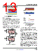
15 / 20 page  LTC4372/LTC4373 15 Rev. 0 For more information www.analog.com APPLICATIONS INFORMATION Figure 11 demonstrates how UV can be used to monitor IN. For the UV pin, the maximum input leakage current is 50nA. For a maximum error of 1% due to leakage cur- rents, the resistive voltage divider current IRVD should be at least 100 times the sum of the leakage currents, or 5μA. The IN Undervoltage threshold (VH2L) is used to calculate the value of R4, R5 and Undervoltage Recovery threshold (VL2H) as shown in Equation 5. VH2L = VUV • R4 +R5 R5 VL2H = VUV + VUV(HYST) ( )•R4+R5 R5 (5) For applications that require a higher and more accurate hysteresis, UVOUT can be used to program an external hysteresis to override the default hysteresis. Comparator C1 in the Block Diagram controls an internal 140Ω switch pulling down on UVOUT. When UV ramps below 1.191V Figure 11. Configuration for Monitoring IN C1 100nF R5 R4 R6 (OPTIONAL) VIN COUT 10µF IN UV INTVCC UVOUT SOURCE LTC4373 GATE OUT 43723 F11 GND and trips C1, the switch pulls UVOUT low. When UV ramps above 1.191V and un-trips C1, the switch turns off and UVOUT goes high impedance. By connecting R6 between UV and UVOUT, R4 and R5 implements VH2L and VL2H. Obtain R4 and R5 from Equation 5 and calculate R6 using Equation 6. VH2L = VUV • R4 +R5 R5 VL2H = VUV • R4 +Rpa Rpa where Rpa = R5//R6 = R5 •R6 R5 +R6 (6) As long as the external hysteresis to be implemented exceeds 5% of VH2L, Equation 6 can disregard the default UV hysteresis without affecting accuracy. With UVOUT connected to the resistive voltage divider, the leakage current error needs to be re-visited. For the UVOUT pin, the maximum input leakage current below 85°C is 50nA. While IN ramps high to low, the resistive voltage divider sees the leakage currents from both UV and UVOUT. This gives a total of 100nA of leakage cur- rents. With 5μA through R4 and R5, this will add 2% inaccuracy to VH2L. While IN ramps low to high, UVOUT is pulled low. The resistive voltage divider sees only the 50nA of leakage current from UV. With 5μA through R4 and R5, this will add 1% inaccuracy to VL2H. To lower the leakage current error, increase IRVD. Layout Considerations Connect IN, SOURCE and OUT as close as possible to the MOSFET source and drain pins. Keep the drain and source traces to the MOSFET wide and short to mini- mize resistive losses as shown in Figure 12. Place COUT close to the drain pin of MOSFET and keep the trace from LTC4372/LTC4373 GATE pin to MOSFET gate short and thin to minimize parasitic inductance and capacitance. This practice will reduce the chance of MOSFET parasitic oscillations. Place any surge suppressors and necessary transient protection components close to the LTC4372/ LTC4373 using short lead lengths. For the DFN package, pin spacing may be a concern at voltages greater than 30V. Check creepage and clearance guidelines to determine if this is an issue. To increase the effective pin spacing between high voltage and ground pins, leave the exposed pad connection open. Use no-clean flux to minimize PCB contamination. |
|
|
链接网址 |
| ALLDATASHEET是否为您带来帮助? [ DONATE ] |
关于 Alldatasheet | 广告服务 | 联系我们 | 隐私政策 | 数据表链接 | 链接交换 | 制造商名单 All Rights Reserved©Alldatasheet.com |
| Russian : Alldatasheetru.com | Korean : Alldatasheet.co.kr | Spanish : Alldatasheet.es | French : Alldatasheet.fr | Italian : Alldatasheetit.com Portuguese : Alldatasheetpt.com | Polish : Alldatasheet.pl | Vietnamese : Alldatasheet.vn Indian : Alldatasheet.in | Mexican : Alldatasheet.com.mx | British : Alldatasheet.co.uk | New Zealand : Alldatasheet.co.nz |
|
Family Site : ic2ic.com |
icmetro.com |
 Chinese ▼
 English
 Chinese
 German
 Japanese
 Russian
 Korean
 Spanish
 French
 Italian
 Portuguese
 Polish
 Vietnamese
 Indian
 Mexican
 British
 New Zealand