|
数据搜索系统,热门电子元器件搜索 |
|
|
数据搜索系统,热门电子元器件搜索 |
|
ADBMS1818ASWZ-R7 数据表(PDF) 21 Page - Analog Devices |
|
|
|||||||||||||||||||||||||||||
ADBMS1818ASWZ-R7 数据表(HTML) 21 Page - Analog Devices |
|
|
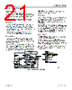
21 / 89 page  Data Sheet ADBMS1818 THEORY OF OPERATION analog.com Rev. 0 | 21 of 89 STATE DIAGRAM The operation of the ADBMS1818 is divided into two separate sections: the core circuit and the isoSPI circuit. Both sections have an independent set of operating states, as well as a shutdown timeout. ADBMS1818 CORE STATE DESCRIPTIONS Sleep State The reference and ADCs are powered down. The watchdog timer (see the Watchdog and Discharge Timer section) has timed out. The discharge timer is either disabled or timed out. The supply currents are reduced to minimum levels. The isoSPI ports are in the idle state. The DRIVE pin is 0 V. If a wake-up signal is received (see the Waking Up the Serial Interface section), the ADBMS1818 enters the standby state. Standby State The reference and the ADCs are off. The watchdog timer and/or the discharge timer is running. The DRIVE pin powers the VREG pin to 5 V through an external transistor. Alternatively, VREG can be powered by an external supply. When a valid ADC command is received or the REFON bit is set to 1 in Configuration Register Group A, the IC pauses for tREFUP to allow the reference to power up and then enters either the REFUP or measure state. Otherwise, if no valid commands are received for tSLEEP (when both the watchdog and discharge timer expire), the ADBMS1818 returns to the sleep state. If the discharge timer is disabled, only the watchdog timer is relevant. REFUP State To reach this state, the REFON bit in Configuration Register Group A must be set to 1 (using the WRCFGA command, see Table 50). The ADCs are off. The reference is powered up so that the ADBMS1818 can initiate ADC conversions more quickly than from the standby state. When a valid ADC command is received, the IC goes to the measure state to begin the conversion. Otherwise, the ADBMS1818 returns to the standby state when the REFON bit is set to 0, either manually (using WRCFGA command) or automatically when the watchdog timer expires (the ADBMS1818 then moves straight into the sleep state if both timers are expired). Measure State The ADBMS1818 performs ADC conversions in the measure state. The reference and ADCs are powered up. After ADC conversions complete, the ADBMS1818 transitions to either the REFUP or standby state, depending on the REFON bit. Additional ADC conversions can be initiated more quickly by setting REFON = 1 to take advantage of the REFUP state. Note that non ADC commands do not cause a core state transition. Only an ADC conversion or diagnostic commands place the core in the measure state. Figure 53. ADBMS1818 Operation State Diagram |
|
链接网址 |
| ALLDATASHEET是否为您带来帮助? [ DONATE ] |
关于 Alldatasheet | 广告服务 | 联系我们 | 隐私政策 | 数据表链接 | 链接交换 | 制造商名单 All Rights Reserved©Alldatasheet.com |
| Russian : Alldatasheetru.com | Korean : Alldatasheet.co.kr | Spanish : Alldatasheet.es | French : Alldatasheet.fr | Italian : Alldatasheetit.com Portuguese : Alldatasheetpt.com | Polish : Alldatasheet.pl | Vietnamese : Alldatasheet.vn Indian : Alldatasheet.in | Mexican : Alldatasheet.com.mx | British : Alldatasheet.co.uk | New Zealand : Alldatasheet.co.nz |
|
Family Site : ic2ic.com |
icmetro.com |
 Chinese ▼
 English
 Chinese
 German
 Japanese
 Russian
 Korean
 Spanish
 French
 Italian
 Portuguese
 Polish
 Vietnamese
 Indian
 Mexican
 British
 New Zealand