INGT165B / INGR165B
10/2003 - rev. 2.0
2 of 21
1. GigaSTaR®® LINK DESCRIPTION
The GigaSTaR® link is designed for reliable, high-speed, low-latency data transmission.
All functions for data transfer management including the high-frequency blocks are fully integrated in the
Transmitter and Receiver devices. Both devices feature a 36-bit “user-friendly” parallel interface with
standard logic levels (3.3V CMOS) for easy adaptation to any application.
The link supports an effective (sustained) data rate up to 148.5 MByte/s at the parallel interface, which
translates to a serial bit stream of max. 1.188 Gbit/s (payload data rate). With 4 additional bits for link-
synchronization, DC-balancing and parity check the maximum bit rate at the serial I/Os is 1.32Gbit/s, for an
overall link efficiency of 90 percent. With only 40 ns propagation delay time each for the Transmitter and
Receiver, the typical overall latency for a GigaSTaR® link with STP copper cable is:
latency [ns] = 2 * 40 ns + 4ns/m * cable-length [m]
For example, the latency is about 160 ns for a 20 meter connection with Shielded-Twisted-Pair (STP)
copper cable.
1.1 CLOCK SYSTEM
The serial bit clock frequency of 1320 MHz is generated by internal PLLs. The Transmitter and Receiver
each require an external 66 MHz reference clock.
A continuous phase alignment in the Receiver ensures that the receive clock is synchronous to the
transmit clock.
1.2 PARALLEL DATA FORMAT
Both the GigaSTaR® Transmitter and Receiver feature a synchronous 36 bit parallel interface. The
maximum frequency at this interface is 33 MHz, equivalent to a period of 30.3 ns for the WRCLK/ RDCLK
signals.
Additional parity I/Os allow the transfer of an optional external parity bit synchronous with the parallel data.
If an external parity bit is provided, the Transmitter validates the signal before the start of the transmission.
If no external parity bit is available, the Transmitter generates this signal automatically.
Parity error flags are provided at both the Transmitter and Receiver devices.
1.3 SERIAL DATA FORMAT
The serial data stream is DC-balanced to support capacitive (AC) coupling for full DC isolation of the link.
This is performed by proprietary coding in the Transmitter device.
1.4 LINK MEDIA (COPPER OR FIBER)
The GigaSTaR® Transmitter and Receiver are each equipped with a robust high-speed interface which can
be directly connected to impedance-controlled cables (STP or coax), transmission lines or fiber optic
modules.
Initial evaluations with 50 Ohm (100 Ohm differential) Shielded-Twisted-Pair (STP) cables already have
proven reliable transmissions at distances of up to 50 meters and beyond (Reference-product:
GGSC1608-05/-10/-15/-20/-30/-40/-50, W.L. Gore & Associates).
Copper media require a serial line termination (R/L combination) at the inputs of the GigaSTaR® Receiver
for optimized performance, please refer to the ING_TRC piggyback board data sheet for reference values.
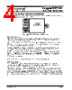
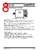
The capacitors for AC coupling of the serial lines have to be 100nF and are to be applied at both ends of
the link medium (see also figure 1). It is required to use ceramic RF capacitors.
With conventional 850 nm fiber optic modules (AC in/out, 3.3V PECL) and multimode fiber distances up to
550 meters have been achieved, see also datasheet of the ING_TRF fiberoptical piggyback board.

 Chinese ▼
 English
 Chinese
 German
 Japanese
 Russian
 Korean
 Spanish
 French
 Italian
 Portuguese
 Polish
 Vietnamese
 Indian
 Mexican
 British
 New Zealand