5 / 21 page
INGT165B / INGR165B
10/2003 - rev. 2.0
5 of 21
2.2.3 Data Burst Transfers
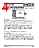
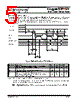
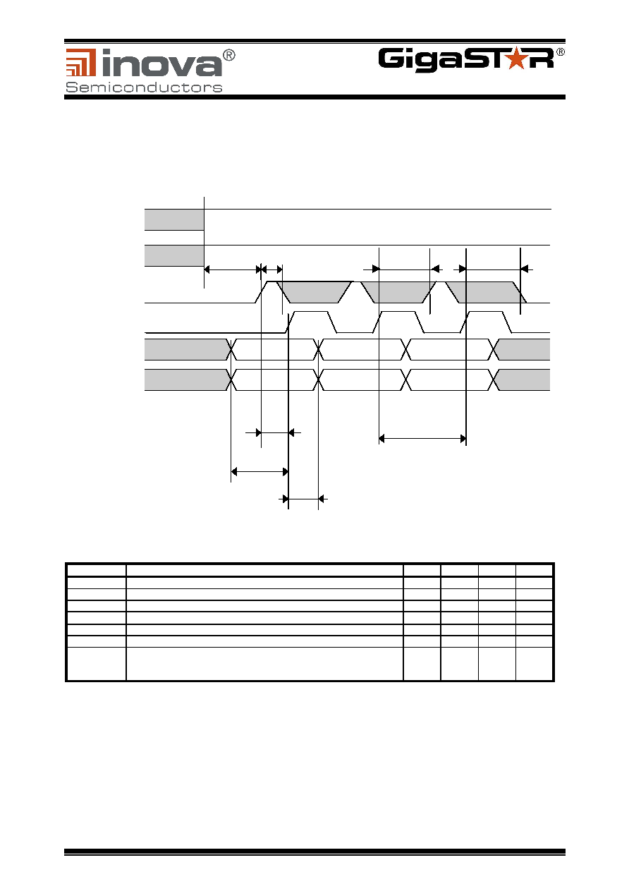
The data burst timing provides the full data rate of 148.5 MByte/s. VALID is asserted when the first data is
valid at PDATA[35.0]. With every rising edge of RDCLK the PDATA inputs are registered, serialized and
transmitted. VALID can remain asserted as long as new data are available.
In the timing diagram PARGEN is de-asserted and the application delivers the PARITY bit synchronously
to the data word.
Figure 4: INGT165B Data Burst Timing Diagram
Parameter
Description
Min.
Typ.
Max.
Unit
t1
Setup time PDATA and PARITY to RDCLK rising edge
9
6
ns
t2
VALID active to first rising RDCLK edge
9
12
14
ns
t2-1
VALID high state
5
4
ns
t2-2
LOCK# / RESET# high state before Tx operational *
50
µs
t3
PDATA and PARITY hold time
9
6
ns
t4
RDCLK cycle time (without assertion of FLAGI)
30.3
ns
t5
Rising RDCLK edge to sampling window for VALID state
(VALID=0: exit BURST mode,
VALID=1: continue BURST mode)
18
20
22
ns
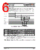
Note : For timings with assertion of FLAGI, please see section 3.2.5
*A dislock pulse generates an internal transmitter reset. Therefore both signals have to be at least
50us at high state before transmitter is operational.
Table 1: INGT165B Data Burst Timing Parameters (under recommended operating conditions)
VALID
RDCLK
PDATA [35..0]
PARITY
DW1
t1
t2
t3
DW2
DW3
t4
PARITY1
PARITY2
PARITY3
t2-1
t5
t5
RESET#
t2-2
LOCK#

 Chinese ▼
 English
 Chinese
 German
 Japanese
 Russian
 Korean
 Spanish
 French
 Italian
 Portuguese
 Polish
 Vietnamese
 Indian
 Mexican
 British
 New Zealand