INGT165B / INGR165B
10/2003 - rev. 2.0
8 of 21
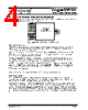
3.2 INGR165B RECEIVER PARALLEL INTERFACE
GigaST#R
INGR165B
RECEIVER
EQLSEL
LSYNC#
FLAGO
RESET#
WRCLK
PDATA[35..0]
PARITY
PERR#
LOCK
SDATA
SDATA#
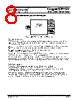
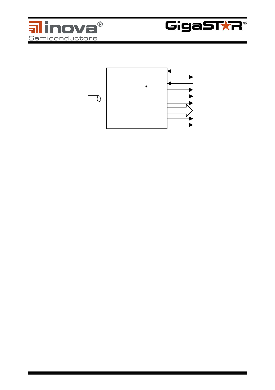
Figure 7: GigaSTaR® Receiver Parallel Interface
3.2.1 Control Signals
RESET# is an asynchronous active low reset signal. After a power-up sequence and activation of the
reference clock, RESET# has to be kept low for at least 1 ms. The link is operational as soon as the
LSYNC# signal is going low.
LOCK = '1' indicates that the internal PLL is locked. If LOCK is de-asserted, the Receiver is not ready.
EQLSEL activates the internal equalizer to support extended cable lengths above 10 meters.
FLAGO is the sideband signalling output flag, for timing details see 3.2.5.
The default state of FLAGO after reset is ‘0’.
The status bit LSYNC# is asserted if the GigaSTaR® Receiver is synchronized to the incoming bit-stream.
If the Receiver is not synchronized correctly, LSYNC# is de-asserted.
The receiver permanently computes the parity over each transmitted word and compares it with the
transmitted parity bit. A mismatch of both parity information indicates a transmission failure and the signal
PERR# is asserted for one data cycle. LSYNC# is de-asserted and the Receiver starts to re-synchronize
the link.
3.2.2 Data Interface
The parallel interface is designed to support a variety of application interfaces.
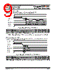
It provides a sequence of write clock (WRCLK) pulses with a cycle time of 30.3 ns
(corresponding to 33MHz) which is used to clock data into the remote application's input buffer
like a FIFO, memory devices or directly into an ASIC or PLD.
A data word at the parallel interface consists of 36 data bits. The data's parity is always available
synchronous to the data at the PARITY output. The application may use the parity bit for additional
information about the data's validity. As long as data with a wrong parity are transmitted, the Receiver
is not synchronized with the Transmitter, and the LSYNC# signal is de-asserted.

 Chinese ▼
 English
 Chinese
 German
 Japanese
 Russian
 Korean
 Spanish
 French
 Italian
 Portuguese
 Polish
 Vietnamese
 Indian
 Mexican
 British
 New Zealand