|
数据搜索系统,热门电子元器件搜索 |
|
|
数据搜索系统,热门电子元器件搜索 |
|
CC2550-RTY1 数据表(PDF) 34 Page - Texas Instruments |
|
|
|
|||||||||||||||||||||||||||||
CC2550-RTY1 数据表(HTML) 34 Page - Texas Instruments |
|
|
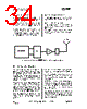
34 / 55 page  CC2550 PRELIMINARY Data Sheet (Rev.1.2) SWRS039A Page 34 of 54 26.7 Low Cost Systems As the CC2550 provides 500 kbps multi- channel performance without any external filters, a very low cost system can be made. A differential antenna will eliminate the need for a balun, and the DC biasing can be achieved in the antenna topology, see Figure 3. A HC-49 type SMD crystal is used in the CC2550EM reference design. Note that the crystal package strongly influences the price. In a size constrained PCB design a smaller, but more expensive, crystal may be used. 26.8 Battery Operated Systems In low power applications, the SLEEP state should be used when the CC2550 is not active. 26.9 Increasing Output Power In some applications it may be necessary to extend the link range by adding an external power amplifier. The power amplifier should be inserted between the antenna and the balun as shown in Figure 20. Figure 20. Block diagram of CC2550 usage with external power amplifier 27 Configuration Registers The configuration of CC2550 is done by programming 8-bit registers. The configuration data based on selected system parameters are most easily found by using the SmartRF® Studio software. Complete descriptions of the registers are given in the following tables. After chip reset, all the registers have default values as shown in the tables. There are 9 Command Strobe Registers, listed in Table 23. Accessing these registers will initiate the change of an internal state or mode. There are 29 normal 8-bit Configuration Registers, listed in Table 24. Many of these registers are for test purposes only, and need not be written for normal operation of CC2550. There are also 6 Status registers, which are listed in Table 25. These registers, which are read-only, contain information about the status of CC2550. The TX FIFO is accessed through one 8-bit register. Only write operations are allowed to the TX FIFO. During the address transfer and while writing to a register or the TX FIFO, a status byte is returned. This status byte is described in Table 15 on page 15. Table 26 summarizes the SPI address space. Registers that are only defined on the CC2500 transceiver are also listed. CC2500 and CC2550 are register compatible, but registers and fields only implemented in the transceiver always contain 0 in CC2550. The address to use is given by adding the base address to the left and the burst and read/write bits on the top. Note that the burst bit has different meaning for base addresses above and below 0x2F. |
|
链接网址 |
| ALLDATASHEET是否为您带来帮助? [ DONATE ] |
关于 Alldatasheet | 广告服务 | 联系我们 | 隐私政策 | 数据表链接 | 链接交换 | 制造商名单 All Rights Reserved©Alldatasheet.com |
| Russian : Alldatasheetru.com | Korean : Alldatasheet.co.kr | Spanish : Alldatasheet.es | French : Alldatasheet.fr | Italian : Alldatasheetit.com Portuguese : Alldatasheetpt.com | Polish : Alldatasheet.pl | Vietnamese : Alldatasheet.vn Indian : Alldatasheet.in | Mexican : Alldatasheet.com.mx | British : Alldatasheet.co.uk | New Zealand : Alldatasheet.co.nz |
|
Family Site : ic2ic.com |
icmetro.com |
 Chinese ▼
 English
 Chinese
 German
 Japanese
 Russian
 Korean
 Spanish
 French
 Italian
 Portuguese
 Polish
 Vietnamese
 Indian
 Mexican
 British
 New Zealand