|
数据搜索系统,热门电子元器件搜索 |
|
|
数据搜索系统,热门电子元器件搜索 |
|
CC2550-RTY1 数据表(PDF) 27 Page - Texas Instruments |
|
|
|
|||||||||||||||||||||||||||||
CC2550-RTY1 数据表(HTML) 27 Page - Texas Instruments |
|
|
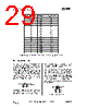
27 / 55 page  CC2550 PRELIMINARY Data Sheet (Rev.1.2) SWRS039A Page 27 of 54 If any frequency programming register is altered when the frequency synthesizer is running, the synthesizer may give an undesired response. Hence, the frequency programming should only be updated when the radio is in the IDLE state. 19 VCO The VCO is completely integrated on-chip. 19.1 VCO and PLL Self-Calibration The VCO characteristics will vary with temperature and supply voltage changes, as well as the desired operating frequency. In order to ensure reliable operation, CC2550 includes frequency synthesizer self-calibration circuitry. This calibration should be done regularly, and must be performed after turning on power and before using a new frequency (or channel). The number of XOSC cycles for completing the PLL calibration is given in Table 18 on page 25. The calibration can be initiated automatically or manually. The synthesizer can be automatically calibrated each time the synthesizer is turned on, or each time the synthesizer is turned off. This is configured with the MCSM0.FS_AUTOCAL register setting. In manual mode, the calibration is initiated when the SCAL command strobe is activated in the IDLE mode. The calibration values are not maintained in sleep mode. Therefore, the CC2550 must be recalibrated after reprogramming the configuration registers when the chip has been in the SLEEP state. To check that the PLL is in lock the user can program register IOCFGx.GDOx_CFG to 0x0A and use the lock detector output available on the GDOx pin as an interrupt for the MCU (x = 0,1 or 2). A positive transition on the GDOx pin means that the PLL is in lock. As an alternative the user can read register FSCAL1. The PLL is in lock if the register content is different from 0x3F. For more robust operation the source code could include a check so that the PLL is re-calibrated until PLL lock is achieved if the PLL does not lock the first time. 20 Voltage Regulators CC2550 contains several on-chip linear voltage regulators, which generate the supply voltage needed by low-voltage modules. These voltage regulators are invisible to the user, and can be viewed as integral parts of the various modules. The user must however make sure that the absolute maximum ratings and required pin voltages in Table 1 and Table 11 are not exceeded. The voltage regulator for the digital core requires one external decoupling capacitor. Setting the CSn pin low turns on the voltage regulator to the digital core and starts the crystal oscillator. The SO pin on the SPI interface must go low before using the serial interface (setup time is given in Table 14). If the chip is programmed to enter power-down mode, (SPWD strobe issued), the power will be turned off after CSn goes high. The power and crystal oscillator will be turned on again when CSn goes low. The voltage regulator output should only be used for driving the CC2550. |
|
链接网址 |
| ALLDATASHEET是否为您带来帮助? [ DONATE ] |
关于 Alldatasheet | 广告服务 | 联系我们 | 隐私政策 | 数据表链接 | 链接交换 | 制造商名单 All Rights Reserved©Alldatasheet.com |
| Russian : Alldatasheetru.com | Korean : Alldatasheet.co.kr | Spanish : Alldatasheet.es | French : Alldatasheet.fr | Italian : Alldatasheetit.com Portuguese : Alldatasheetpt.com | Polish : Alldatasheet.pl | Vietnamese : Alldatasheet.vn Indian : Alldatasheet.in | Mexican : Alldatasheet.com.mx | British : Alldatasheet.co.uk | New Zealand : Alldatasheet.co.nz |
|
Family Site : ic2ic.com |
icmetro.com |
 Chinese ▼
 English
 Chinese
 German
 Japanese
 Russian
 Korean
 Spanish
 French
 Italian
 Portuguese
 Polish
 Vietnamese
 Indian
 Mexican
 British
 New Zealand