|
数据搜索系统,热门电子元器件搜索 |
|
|
数据搜索系统,热门电子元器件搜索 |
|
CC2550-RTY1 数据表(PDF) 28 Page - Texas Instruments |
|
|
|
|||||||||||||||||||||||||||||
CC2550-RTY1 数据表(HTML) 28 Page - Texas Instruments |
|
|
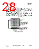
28 / 55 page  CC2550 PRELIMINARY Data Sheet (Rev.1.2) SWRS039A Page 28 of 54 21 Output Power Programming The RF output power level from the device has two levels of programmability, as illustrated in Figure 18. Firstly, the special PATABLE register can hold up to eight user selected output power settings. Secondly, the 3-bit FREND0.PA_POWER value selects the PATABLE entry to use. This two-level functionality provides flexible PA power ramp up and ramp down at the start and end of transmission. All the PA power settings in the PATABLE from index 0 up to the FREND0.PA_POWER value are used. The power ramping at the start and at the end of a packet can be turned off by setting FREND0.PA_POWER to 0 and then programming the desired output power to index 0 in the PATABLE. Table 20 contains recommended PATABLE settings for various output levels and frequency bands. See Section 10.6 on page 16 for PATABLE programming details. PATABLE must be programmed in burst mode if you want to write to other entries than PATABLE[0]. e.g 6 PA_POWER[2:0] in FREND0 register PATABLE(0)[7:0] PATABLE(1)[7:0] PATABLE(2)[7:0] PATABLE(3)[7:0] PATABLE(4)[7:0] PATABLE(5)[7:0] PATABLE(6)[7:0] PATABLE(7)[7:0] Index into PATABLE(7:0) The PA uses this setting. Settings 0 to PA_POWER are used during ramp-up at start of transmission and ramp-down at end of transmission, and for OOK modulation. The SmartRF® Studio software should be used to obtain optimum PATABLE settings for various output powers. Figure 18: PA_POWER and PATABLE |
|
链接网址 |
| ALLDATASHEET是否为您带来帮助? [ DONATE ] |
关于 Alldatasheet | 广告服务 | 联系我们 | 隐私政策 | 数据表链接 | 链接交换 | 制造商名单 All Rights Reserved©Alldatasheet.com |
| Russian : Alldatasheetru.com | Korean : Alldatasheet.co.kr | Spanish : Alldatasheet.es | French : Alldatasheet.fr | Italian : Alldatasheetit.com Portuguese : Alldatasheetpt.com | Polish : Alldatasheet.pl | Vietnamese : Alldatasheet.vn Indian : Alldatasheet.in | Mexican : Alldatasheet.com.mx | British : Alldatasheet.co.uk | New Zealand : Alldatasheet.co.nz |
|
Family Site : ic2ic.com |
icmetro.com |
 Chinese ▼
 English
 Chinese
 German
 Japanese
 Russian
 Korean
 Spanish
 French
 Italian
 Portuguese
 Polish
 Vietnamese
 Indian
 Mexican
 British
 New Zealand