|
数据搜索系统,热门电子元器件搜索 |
|
|
数据搜索系统,热门电子元器件搜索 |
|
AD604ARSZ-R7 数据表(PDF) 24 Page - Analog Devices |
|
|
|||||||||||||||||||||||||||||
AD604ARSZ-R7 数据表(HTML) 24 Page - Analog Devices |
|
|
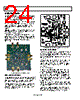
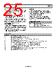
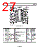
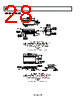
24 / 32 page  AD604 Rev. D | Page 24 of 32 EVALUATION BOARD Figure 55 is a photograph of the AD604 evaluation board assembly. Multiple input connections, test points, jumper selectable options, and on-board trims offer convenience when configuring the AD604 in various operating modes. The evaluation board requires only a dual 5 V supply capable of 200 mA or higher to operate both channels. Prior to shipment, the evaluation board is fully tested. Users need only attach power supply leads and the appropriate test equipment to the board. Because of this flexibility, not all component positions on the board are populated when the board is shipped. Installing or changing additional parts is optional. The AD604-EVAL is fabricated on a 4-layer board with inner power and ground layers. The AD604 is a stable, trouble-free device; however, as with all high frequency integrated circuits, power and ground planes help to ensure consistency in performance. Figure 55. AD604 Evaluation Board Assembly USING THE PREAMPLIFIER To use the preamplifiers, simply connect a signal source to CH1 PREAMP IN and/or CH2 PREAMP IN via the SMA connectors. Referring to the schematic in Figure 61, the input lines are terminated with 50 Ω resistors at locations R7 and R8. To enable the preamplifiers, insert jumpers in the JP8 and JP9 rightmost positions; this connects COM1 and COM2 to ground. Power down the preamplifiers by inserting jumpers in the JP8 and JP9 leftmost positions. Figure 56. AD604 Evaluation Board—Component Side Silk Screen DSX INPUT CONNECTIONS The DSX inputs can be connected in single-ended or differential configurations. SMA connectors are provided for each of the inputs and are labeled CH1, CH2, VGA IN (+), and VGA IN (−). JP6 and JP15 select between the preamplifier outputs and the DSX inputs. For direct drive of the Channel 1 VGA, insert a jumper in the top position of JP6. For direct drive of the Channel 2 VGA, insert a jumper in JP14 and verify that there are no jumpers in JP12 and JP13. Refer to the schematic shown in Figure 61 for circuit details. Differential DSX Inputs Differential inputs are possible using both polarities of the VGA SMA connectors and appropriate jumpers. Inserting a jumper in the lower position of JP5 selects the negative input of Channel 1. A jumper in the top position of JP6 selects the positive input of Channel 1. A jumper in the JP16 rightmost position selects the negative input of Channel 2, and a jumper in JP14 selects the positive input. Again, verify that there are no jumpers in JP15 or JP13. Because the VGA section of the AD604 uses a single 5 V supply, the DSX inputs are ac-coupled. Decoupling capacitors are provided on the evaluation board. The DSX input impedance is approximately 200 Ω. Optional 66.5 Ω resistors can be installed across the inputs at positions R5, R6, R9, and R10 to establish a 50 Ω terminating load. |
|
链接网址 |
| ALLDATASHEET是否为您带来帮助? [ DONATE ] |
关于 Alldatasheet | 广告服务 | 联系我们 | 隐私政策 | 数据表链接 | 链接交换 | 制造商名单 All Rights Reserved©Alldatasheet.com |
| Russian : Alldatasheetru.com | Korean : Alldatasheet.co.kr | Spanish : Alldatasheet.es | French : Alldatasheet.fr | Italian : Alldatasheetit.com Portuguese : Alldatasheetpt.com | Polish : Alldatasheet.pl | Vietnamese : Alldatasheet.vn Indian : Alldatasheet.in | Mexican : Alldatasheet.com.mx | British : Alldatasheet.co.uk | New Zealand : Alldatasheet.co.nz |
|
Family Site : ic2ic.com |
icmetro.com |
 Chinese ▼
 English
 Chinese
 German
 Japanese
 Russian
 Korean
 Spanish
 French
 Italian
 Portuguese
 Polish
 Vietnamese
 Indian
 Mexican
 British
 New Zealand