|
数据搜索系统,热门电子元器件搜索 |
|
|
数据搜索系统,热门电子元器件搜索 |
|
AD604ARSZ-R7 数据表(PDF) 25 Page - Analog Devices |
|
|
|||||||||||||||||||||||||||||
AD604ARSZ-R7 数据表(HTML) 25 Page - Analog Devices |
|
|
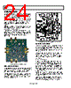
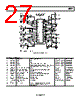
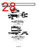
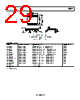
25 / 32 page  AD604 Rev. D | Page 25 of 32 Connecting the DSX Inputs to the Preamplifiers To connect the DSX inputs to the preamplifiers, install jumpers in the JP6 lower position and in JP15. Verify that the jumpers in JP13 and JP14 are removed. Cascaded DSX To channel cascade the two channels, insert a jumper in JP13. The resulting single channel gain range is 96 dB. Verify that JP14 and JP15 are removed. The gains of cascaded VGAs can be controlled independently or in common. For common control, insert a jumper in the top position of JP4. To use the trimmer as a gain control, insert a jumper in JP1. For external control, remove JP1 and connect a signal source at test loop VGN1 or VGN2. PREAMPLIFIER GAIN Jumpers in JP7 and JP12 select between two preamplifier gains: 14 dB and 20 dB. Intermediate gains are derived by installing resistors in positions R11 and R12. The 14 dB and 20 dB preset gains are accurate due to close matching of thin film resistors. The gain accuracy after installing external resistors is subject to inherent tolerance of absolute accuracy. OUTPUTS The DSX outputs are available on OUT1 and OUT2 SMA connectors and are series terminated with decoupling capacitors and 49.9 Ω series resistors. These components can be replaced to accommodate other output impedances. DC OPERATING CONDITIONS Table 4 lists the trimmers and their functions provided for convenient dc level adjustments of gain, reference voltage, and output common-mode voltage. Table 5 lists the jumpers and their functions. Table 4. Trimmer Functions Trimmer Function R1 Gain of Channel 1 R2 Reference voltage adjustment R3 Output common-mode voltage adjustment R4 Channel 2 gain adjustment Table 5. Jumpers Jumper No. Function 1 Connects R1 gain adjust wiper to VGN1 2 Connects R2 reference voltage trimmer to VREF input 3 Connects common-mode voltage trimmer to VOCM 4 Connects VGN2 to R4 Channel 2 gain trimmer or to VGN1 or common gain adjustment 5 Connects –DSX1 to CH1 VGA IN (−) or to ground 6 Connects +DSX1 (ac-coupled) to preamplifier output of Channel 1 or to the CH 1 VGA IN (+) SMA connector 7 When open, the Preamp 1 Gain is 20 dB; Preamp Gain 1 is 14 dB when a shunt is installed 8 Shunt in left position disables Preamp 1; shunt in rightmost position enables Preamp 1 9 Shunt in left position disables Preamp 2; shunt in rightmost position enables Preamp 2 12 When open, the Preamp 2 gain is 20 dB; Preamp 2 gain is 14 dB when a shunt is installed 13 Cascades DSX2 with DSX 1 when a jumper is inserted 14 Connects +DSX2 (ac-coupled) to preamplifier output of Channel 2 or to the CH 2 VGA IN (+) SMA connector 15 Connects +DSX2 (ac-coupled) to preamplifier output of Channel 2 16 Connects –DSX2 to CH2 VGA IN (−) or to ground |
|
链接网址 |
| ALLDATASHEET是否为您带来帮助? [ DONATE ] |
关于 Alldatasheet | 广告服务 | 联系我们 | 隐私政策 | 数据表链接 | 链接交换 | 制造商名单 All Rights Reserved©Alldatasheet.com |
| Russian : Alldatasheetru.com | Korean : Alldatasheet.co.kr | Spanish : Alldatasheet.es | French : Alldatasheet.fr | Italian : Alldatasheetit.com Portuguese : Alldatasheetpt.com | Polish : Alldatasheet.pl | Vietnamese : Alldatasheet.vn Indian : Alldatasheet.in | Mexican : Alldatasheet.com.mx | British : Alldatasheet.co.uk | New Zealand : Alldatasheet.co.nz |
|
Family Site : ic2ic.com |
icmetro.com |
 Chinese ▼
 English
 Chinese
 German
 Japanese
 Russian
 Korean
 Spanish
 French
 Italian
 Portuguese
 Polish
 Vietnamese
 Indian
 Mexican
 British
 New Zealand