|
数据搜索系统,热门电子元器件搜索 |
|
|
数据搜索系统,热门电子元器件搜索 |
|
STDRIVEG611QTR 数据表(PDF) 17 Page - STMicroelectronics |
|
|
|||||||||||||||||||||||||||||
STDRIVEG611QTR 数据表(HTML) 17 Page - STMicroelectronics |
|
|
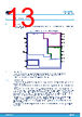
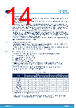
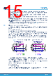
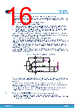
17 / 33 page  An integrated bootstrap diode is there to generate floating supply voltage for the high-side structure. 6.4.1 VCC supply structure and relevant UVLO protection The VCC pin supplies the logic circuit, the input structure of the low-side driver and the integrated bootstrap structure (DBOOT). Low-ESR ceramic capacitors must be connected as close as possible between VCC and GND (100 nF typ., X7R). A bulk capacitor is recommended on VCC to deliver the impulsive bootstrap current to charge VBO. A single VCC rail electrolytic capacitor is typically sufficient even with multiple drivers on board while using only the integrated bootstrap diode and the electrolytic capacitor is not too far. Dedicated bigger low-ESR ceramic VCC capacitors are otherwise recommended, also in the case of an optional external bootstrap diode to minimize VCC dips. An external bootstrap diode could be required for those applications requiring a faster high-side startup time (such as burst mode). Undervoltage protection is available on the VCC supply pin. A hysteresis sets the turn-off threshold. When VCC voltage reaches the VCCthON threshold, the device enters normal operation: if VLS is above UVLO level and the STBY pin is high, the FLT pin is released and the device sets drivers output according to actual input pins; high-side driver supply state is not monitored, therefore the high-side driver generates driving levels when VHS is above UVLO level. When VCC voltage goes below the VCCthOFF threshold, both high-side and low-side gate driver outputs are forced low and the FLT pin is forced low to signal the state to remote controllers. The minimum VCC voltage that the STDRIVEG611 requires to be able to force the FLT pin low is VVCC-FLT. In hard switching applications, during deadtime and load current flowing out from the OUT node, low-side GaN is in reverse conduction mode (as a freewheeling diode) and the OUT pin becomes negative with several volts below GND. GaN transistors do not have an intrinsic body diode, which have the benefit of 0 nC recovery charge, but have worse reverse conduction characteristics in respect to MOSFETs. This could lead to two drawbacks if not properly addressed: • higher GaN dissipation during deadtime, that should be minimized. • deeper static below-GND voltage on OUT node during deadtime; this could bring BOOT lower than the recommended operating range (BOOT-GND min. 5 V), increasing high-side hard turn-on propagation delay. To help ensure BOOT in the recommended operating range in hard switching applications (while current is freewheeling in low-side GaN), the VCC supply has a relatively high UVLO threshold. This helps charging and achieving the VBO > (low-side GaN reverse conduction drop +5 V) recommended range in almost all conditions. Operating with VCC higher than the typical value could be required only in very limited cases where extreme hard switching current transient with very high GaN reverse conduction voltage is foreseen. 6.4.2 VLS supply structure and relevant UVLO protection The integrated VCCL regulator reduces the input VCC voltage to a regulated VLS (6 V typ.) to drive the gate with a stable and optimized VGS voltage. Low-side regulator input is VCC pin; regulator output is VCCL pin, referred to PGND. Low-ESR ceramic capacitors must be connected as close as possible between VCCL and PGND (CVCCL min. 47 nF, X7R, 16 V) to obtain a clean supply voltage. A slightly higher CVCCL could be required to minimize VLS ripple when driving high GaN QG. Under recommended operating conditions, VCCL regulator can provide an average current of 10 mA. A UVLO on VLS is there to prevent unsafe operations of low-side GaN. When VLS voltage reaches the VLSthON threshold, the device enables the low-side driver normal operation: if no other protection is active, FLT pin is released, and the device sets low-side driver output according to actual input pins and high-side driver output according to actual input pins. When VLS voltage goes below the VLDthOFF threshold, both high-side and low-side gate driver outputs are forced low and the FLT pin is forced low to signal this condition to the remote controllers. STDRIVEG611 Device description DS14457 - Rev 2 page 17/33 |
|
链接网址 |
| ALLDATASHEET是否为您带来帮助? [ DONATE ] |
关于 Alldatasheet | 广告服务 | 联系我们 | 隐私政策 | 数据表链接 | 链接交换 | 制造商名单 All Rights Reserved©Alldatasheet.com |
| Russian : Alldatasheetru.com | Korean : Alldatasheet.co.kr | Spanish : Alldatasheet.es | French : Alldatasheet.fr | Italian : Alldatasheetit.com Portuguese : Alldatasheetpt.com | Polish : Alldatasheet.pl | Vietnamese : Alldatasheet.vn Indian : Alldatasheet.in | Mexican : Alldatasheet.com.mx | British : Alldatasheet.co.uk | New Zealand : Alldatasheet.co.nz |
|
Family Site : ic2ic.com |
icmetro.com |
 Chinese ▼
 English
 Chinese
 German
 Japanese
 Russian
 Korean
 Spanish
 French
 Italian
 Portuguese
 Polish
 Vietnamese
 Indian
 Mexican
 British
 New Zealand