|
数据搜索系统,热门电子元器件搜索 |
|
|
数据搜索系统,热门电子元器件搜索 |
|
STDRIVEG611QTR 数据表(PDF) 23 Page - STMicroelectronics |
|
|
|||||||||||||||||||||||||||||
STDRIVEG611QTR 数据表(HTML) 23 Page - STMicroelectronics |
|
|
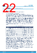
23 / 33 page  7.1.2 Gate resistors The most critical layout part in a GaN design is the gate driving loop: parasitic inductance must be minimized. The path between OUTx → RGATE resistor → GaN gate → GaN (Kelvin) source → PGND/OUT must be minimized. Using 0603 or smaller SMD resistors is recommended also as creating a small copper plane connected to PGND/OUT under the gate routing path to minimize loop inductance. Turn-on gate resistors must be placed as close as possible to VCCH, RONH and VCCL, RONL pins. 7.1.3 Noise reduction To minimize the noise generation during normal operation of typical applications, a few simple steps can be followed: 1. Connect signal GND to current shunt cold pole (or low-side source if shunt is not present) with a single star point. Signal ground consists of controller GND and signal GND of the STDRIVEG611. 2. If a shunt resistor is necessary, this component should have very small ELS and be placed as close as possible to the low-side source and the STDRIVEG611. A cheap alternative to a low ESL resistor consists of the parallel of multiple smaller resistors (for example, 3x 0603 SMD resistors have similar ESL of a 1020 package shunt resistor and is much lower than a 2010 standard package). On motor control applications, with low dV/dt and dI/dt, the requirement can be relaxed, but small SMD shunt resistors are still recommended to minimize ESL to remain in the recommended operating conditions range. 3. In the case of motor control (low dV/dt) applications requiring slowing down hard off dV/dt, a capacitor in parallel to GaN gate could be required. Place the capacitor as close as possible to the GaN pins. If ringing is observed, a resistor in series to these capacitors helps dumping ringing. 4. The OUT pin could be high frequency switching: it is preferable to be routed very closely to the load (in case of transformer or inductor) minimizing the overlap with any other nets. This avoids undesired parasitic capacitance and noise generation. 5. Components connected to BOOT, VCCH, RONH, and OUTH floats together with the OUT node. They must be placed as close as possible to the listed pins minimizing the overlap with other nets. 6. Keep current loops as small as possible. A high voltage ceramic capacitor connected between high voltage bus and power ground and placed as close as possible to GaN devices facilitates the reduction of such loops. In multiphase applications, a ceramic capacitor is recommended for each half-bridge. In high dV/dt hard switching applications, the high voltage ceramic capacitor ground return should be routed preferably just under, or at least beside, the low-side and high-side GaN to minimize loop inductance, ringing, and noise generation. The use of the first inner layer just under the GaN pads is the most effective. Proper dielectric thickness must be selected for the insulation between the two layers. A core foil, instead of prepreg, between the two layers is often used to ensure a more constant thickness in the PCB production process. STDRIVEG611 PCB, BOM, and layout recommendations DS14457 - Rev 2 page 23/33 |
|
链接网址 |
| ALLDATASHEET是否为您带来帮助? [ DONATE ] |
关于 Alldatasheet | 广告服务 | 联系我们 | 隐私政策 | 数据表链接 | 链接交换 | 制造商名单 All Rights Reserved©Alldatasheet.com |
| Russian : Alldatasheetru.com | Korean : Alldatasheet.co.kr | Spanish : Alldatasheet.es | French : Alldatasheet.fr | Italian : Alldatasheetit.com Portuguese : Alldatasheetpt.com | Polish : Alldatasheet.pl | Vietnamese : Alldatasheet.vn Indian : Alldatasheet.in | Mexican : Alldatasheet.com.mx | British : Alldatasheet.co.uk | New Zealand : Alldatasheet.co.nz |
|
Family Site : ic2ic.com |
icmetro.com |
 Chinese ▼
 English
 Chinese
 German
 Japanese
 Russian
 Korean
 Spanish
 French
 Italian
 Portuguese
 Polish
 Vietnamese
 Indian
 Mexican
 British
 New Zealand