|
数据搜索系统,热门电子元器件搜索 |
|
|
数据搜索系统,热门电子元器件搜索 |
|
STDRIVEG611QTR 数据表(PDF) 26 Page - STMicroelectronics |
|
|
|||||||||||||||||||||||||||||
STDRIVEG611QTR 数据表(HTML) 26 Page - STMicroelectronics |
|
|
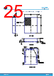
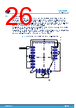
26 / 33 page  8.2 Suggested footprint The STDRIVEG611 footprint for the PCB layout is usually defined based on several design factors such as assembly plant technology capabilities and board component density. For easy device usage and evaluation, STMicroelectronics provides the following footprint design, which is suitable for the largest variety of PCBs. The following footprint indicates the copper area that should be free from the solder mask, while the copper area could extend beyond the indicated areas for device pins, especially GND, PGND, and OUT pins, which is beneficial for thermal and stray inductance minimization purposes. A copper area connected to GND pins aids thermal dissipation, is useful to shield the input signal, and creates a low inductance, good return path for supplying capacitor currents. A copper area connected to PGND and OUT pins running below the related components can minimize gate loop inductance for optimal gate driving and improves the return path for supply capacitor currents. A PCB layout example is available with the STDRIVEG611 evaluation board. Figure 19. QFN 4 x 5 x 1 mm, 18 leads, 0.5 mm pitch, suggested footprint STDRIVEG611 Package information DS14457 - Rev 2 page 26/33 |
|
链接网址 |
| ALLDATASHEET是否为您带来帮助? [ DONATE ] |
关于 Alldatasheet | 广告服务 | 联系我们 | 隐私政策 | 数据表链接 | 链接交换 | 制造商名单 All Rights Reserved©Alldatasheet.com |
| Russian : Alldatasheetru.com | Korean : Alldatasheet.co.kr | Spanish : Alldatasheet.es | French : Alldatasheet.fr | Italian : Alldatasheetit.com Portuguese : Alldatasheetpt.com | Polish : Alldatasheet.pl | Vietnamese : Alldatasheet.vn Indian : Alldatasheet.in | Mexican : Alldatasheet.com.mx | British : Alldatasheet.co.uk | New Zealand : Alldatasheet.co.nz |
|
Family Site : ic2ic.com |
icmetro.com |
 Chinese ▼
 English
 Chinese
 German
 Japanese
 Russian
 Korean
 Spanish
 French
 Italian
 Portuguese
 Polish
 Vietnamese
 Indian
 Mexican
 British
 New Zealand