|
数据搜索系统,热门电子元器件搜索 |
|
|
数据搜索系统,热门电子元器件搜索 |
|
FT600Q-B-R 数据表(PDF) 13 Page - Future Technology Devices International Ltd. |
|
|
|||||||||||||||||||||||||||||
FT600Q-B-R 数据表(HTML) 13 Page - Future Technology Devices International Ltd. |
|
|
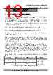
13 / 33 page  Copyright © Future Technology Devices International Limited 13 FT600Q-FT601Q IC DatasheetDatasheet Version 1.04 Document No.: FT_001118 Clearance No.: FTDI#424 0 1 SDP(standard downstream port) detected 1 0 CDP(Charging downstream port) detected 1 1 DCP(Dedicated charging port) detected 4.2 Multi-Channel FIFO mode Protocols This is a Slave bus and is designed to handle multi-channel connectivity. The bus protocol supports a total of 4 bidirectional channels; each has 1 USB OUT and 1 USB IN endpoints. . CLK is the clock output from the bus slave to the bus master. The channel number denoted in this document as channel 1 to 3 mapped to USB endpoint number 2 to 5. The USB OUT endpoint in Channel 1 is denoted as USB out channel 1, USB IN endpoint in channel 1 is denoted as USB IN channel 1. Correspondingly, the FIFO OUT is for data transmitted from USB host to device and FIFO IN is for data transmitted from USB device to host. WR_N is the bus master to bus slave data transaction request signal, and it is active low. RXF_N is the bus slave to bus master data receive acknowledge signal, and it is active low. TXE_N (optional signal, master can ignore this signal) is the bus slave to bus master FIFO idle status valid signal, and it is low active. DATA[31:0] is used as the 32-bit data bus during the data transfer phase. When the bus is in the idle state DATA[31:16], DATA[7:0] and BE[3:0] are driven to logic”1” by the bus master, and DATA[15:8] is driven by the bus slave to provide the FIFO status to the bus master. The upper nibble (DATA[15:12]) provides the 4 OUT channels FIFO status while the lower nibble (DATA[11:8]) provides the 4 IN channels FIFO status. They are all active low. For example, at idle, DATA[12] is logic”0” and DATA[8] is logic”0”, which indicates USB OUT channel 1 FIFO data is available to send and USB IN channel 1 FIFO space is empty to receive data respectively. The external bus master will start a transfer cycle by asserting WR_N based on the channel FIFO status. The first cycle after WR_N is asserted is the command phase, followed by the data phase when RXF_N is asserted. At the command phase, the bus master will send the channel number which it intends to transfer data with on DATA[7:0] and the Read/Write command on BE[3:0]. BE[3:0] = ‘h0 and BE[3:0] = ‘h1 indicates a master read or write respectively. There may also be a required turn-a-round for DATA[31:0] and BE[3:0] after the command phase and at the end of data transaction. BE[1:0] is valid for FT600 2 byte wide data interface. Table 4.1 shows Multi-Channel FIFO mode command phase master read/write and channel address setting. Command Phase FT600 Command BE[1:0] FT601 Command BE[3:0] Channel Address DATA[7:0] Master Read 00 0000 8’h1=Channel 1 8’h2=Channel 2 8’h3=Channel 3 8’h4=Channel 4 Master Write 01 0001 Table 4.1 Multi-Channel FIFO mode Command phase |
|
链接网址 |
| ALLDATASHEET是否为您带来帮助? [ DONATE ] |
关于 Alldatasheet | 广告服务 | 联系我们 | 隐私政策 | 数据表链接 | 链接交换 | 制造商名单 All Rights Reserved©Alldatasheet.com |
| Russian : Alldatasheetru.com | Korean : Alldatasheet.co.kr | Spanish : Alldatasheet.es | French : Alldatasheet.fr | Italian : Alldatasheetit.com Portuguese : Alldatasheetpt.com | Polish : Alldatasheet.pl | Vietnamese : Alldatasheet.vn Indian : Alldatasheet.in | Mexican : Alldatasheet.com.mx | British : Alldatasheet.co.uk | New Zealand : Alldatasheet.co.nz |
|
Family Site : ic2ic.com |
icmetro.com |
 Chinese ▼
 English
 Chinese
 German
 Japanese
 Russian
 Korean
 Spanish
 French
 Italian
 Portuguese
 Polish
 Vietnamese
 Indian
 Mexican
 British
 New Zealand