|
数据搜索系统,热门电子元器件搜索 |
|
|
数据搜索系统,热门电子元器件搜索 |
|
AM2434...ALV 数据表(PDF) 9 Page - Texas Instruments |
|
|
|||||||||||||||||||||||||||||
AM2434...ALV 数据表(HTML) 9 Page - Texas Instruments |
|
|
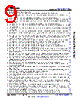
9 / 280 page  • Removed non-applicable TBD values. .......................................................................................................... 123 • Defined the minimum input slew rate value and added notes to describe this parameter..............................123 • (High-Frequency Oscillator (HFOSC) Electrical Characteristics): Defined maximum Input Leakage Current value............................................................................................................................................................... 123 • (SDIO Electrical Characteristics): Added a note to explain the IOL and IOH parameters.................................124 • (SDIO Electrical Characteristics): Removed non-applicable TBD values from 3.3-V mode Input Slew Rate.124 • (SDIO Electrical Characteristics): Defined the minimum input slew rate value and added notes to describe this parameter.................................................................................................................................................124 • (LVCMOS Electrical Characteristics): Added a note to explain the IOL and IOH parameters.......................... 125 • (LVCMOS Electrical Characteristics): Removed non-applicable TBD values from 1.8-V mode and 3.3-V mode Input Slew Rate.............................................................................................................................................. 125 • (LVCMOS Electrical Characteristics): Defined the minimum input slew rate value and added notes to describe this parameter.................................................................................................................................................125 • (ADC12B Electrical Characteristics): Added Positive Reference Voltage and Negative Reference Voltage parameters, with a note that describes connectivity requirements for the ADC0_REFP and ADC0_REFN pins ........................................................................................................................................................................126 • (ADC12B Electrical Characteristics): Changed the Differential Non-Linearity values; the minimum value was changed from -1 to > -1 to indicate there is no missing codes, the typical value was removed, and the maximum value was changed from 2 to +1.................................................................................................... 126 • (ADC12B Electrical Characteristics): Changed the Integral Non-Linearity values; the minimum value was changed to -2, the typical value was removed, and the maximum value was changed from ±3 to +2........... 126 • (ADC12B Electrical Characteristics): Changed the typical Gain Error value from ±2 to ±10..........................126 • (ADC12B Electrical Characteristics): Changed the typical Offset Error value from ±2 to ±5.......................... 126 • (ADC12B Electrical Characteristics): Changed the “Input Sampling Capacitance (CIN)” parameter to “Sampling Capacitance (CSMPL)”, with the same typical value....................................................................... 126 • (ADC12B Electrical Characteristics): Changed the typical Total Harmonic Distortion value from 75 to -75... 126 • (ADC12B Electrical Characteristics): Removed the Spurious Free Dynamic Range and Signal-to-Noise Plus Distortion parameters..................................................................................................................................... 126 • (ADC12B Electrical Characteristics): Changed the “Input Impedance of ADC0_AIN[7:0] (RADC0_AIN[7:0])” parameter to “Analog Input Impedance, ADC0_AIN[7:0] (ZADC0_AIN[7:0])” and replaced the formula for calculating a typical value with a note that clarifies input impedance of the ADC0_AIN[7:0] analog inputs... 126 • (ADC12B Electrical Characteristics): Removed the VSS and VDDA_ADC0 test conditions from the Input Leakage parameter and defined a single maximum value that represents the entire input voltage range of the ADC0_AIN[7:0] analog inputs.........................................................................................................................126 • (ADC12B Electrical Characteristics): Removed the Channel to Channel Isolation parameter....................... 126 • (Recommended Operating Conditions for OTP eFuse Programming): Changed the maximum VPP current value from TBD to 400 mA............................................................................................................................. 128 • (Power Supply Requirements): Updated the section title from "Power Supply Sequencing" to "Power Supply Requirements"................................................................................................................................................ 131 • (Power Supply Sequencing): Added new section and explanation of the two types of power supply transition regions found in the Power-up and Power-down Sequence diagrams...........................................................132 • (MCU_OSC0 Start-up Time): Updated signal names in figure....................................................................... 144 • (CPSW3G): Updated the Note to reference the CPSW3G IOSETs section for the several tables contained within the section............................................................................................................................................ 149 • (GPIO Timing Conditions): Changed the minimum Input Slew rate for the LVCMOS buffer type, and defined Input Slew Rate values for the I2C OD FS buffer type................................................................................... 163 • (GPIO Timing Requirements): Changed the "BUFFER TYPE" column to "MODE", replaced buffer types with operating voltage, retained the minimum pulse width value for 1.8-V mode, and changed the minimum pulse width value for 3.3-V mode............................................................................................................................. 163 • (GPMC and NOR Flash — Synchronous Mode): Updated timing parameters and values............................ 164 • (GPMC and NOR Flash — Synchronous Mode): Changed the "not_div_by_1_mode"minimum value in the "Hold time, input wait GPMC_WAIT[j] valid after output clock GPMC_CLK high (th(clkH-waitV))" parameter from 2.9 to 2.29 to correct a typographical error.....................................................................................................164 • (GPMC and NOR Flash — Asynchronous Mode): Updated timing parameters and values...........................174 • (GPMC and NAND Flash — Asynchronous Mode): Updated timing parameters and values........................ 182 www.ti.com AM2434, AM2432, AM2431 SPRSP65D – APRIL 2021 – REVISED AUGUST 2022 Copyright © 2022 Texas Instruments Incorporated Submit Document Feedback 9 Product Folder Links: AM2434 AM2432 AM2431 |
|
链接网址 |
| ALLDATASHEET是否为您带来帮助? [ DONATE ] |
关于 Alldatasheet | 广告服务 | 联系我们 | 隐私政策 | 数据表链接 | 链接交换 | 制造商名单 All Rights Reserved©Alldatasheet.com |
| Russian : Alldatasheetru.com | Korean : Alldatasheet.co.kr | Spanish : Alldatasheet.es | French : Alldatasheet.fr | Italian : Alldatasheetit.com Portuguese : Alldatasheetpt.com | Polish : Alldatasheet.pl | Vietnamese : Alldatasheet.vn Indian : Alldatasheet.in | Mexican : Alldatasheet.com.mx | British : Alldatasheet.co.uk | New Zealand : Alldatasheet.co.nz |
|
Family Site : ic2ic.com |
icmetro.com |
 Chinese ▼
 English
 Chinese
 German
 Japanese
 Russian
 Korean
 Spanish
 French
 Italian
 Portuguese
 Polish
 Vietnamese
 Indian
 Mexican
 British
 New Zealand