|
数据搜索系统,热门电子元器件搜索 |
|
|
数据搜索系统,热门电子元器件搜索 |
|
AM2434...ALV 数据表(PDF) 17 Page - Texas Instruments |
|
|
|||||||||||||||||||||||||||||
AM2434...ALV 数据表(HTML) 17 Page - Texas Instruments |
|
|
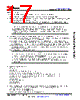
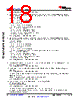
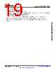
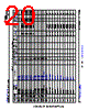
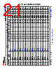
17 / 280 page  6.2 Pin Attributes The following list describes the contents of each column in the Pin Attributes table: 1. Ball Number: Ball numbers assigned to each terminal of the Ball Grid Array package. 2. Ball Name: Ball name assigned to each terminal of the Ball Grid Array package (this name is typically taken from the primary MUXMODE 0 signal function). 3. Signal Name: Signal name of all dedicated and pin multiplexed signal functions associated with a ball. Note The Pin Attributes table, defines the SoC pin multiplexed signal function implemented at the pin and does not define secondary multiplexing of signal functions implemented in device subsystems. Secondary multiplexing of signal functions are not described in this table. For more information on secondary multiplexed signal functions, see the respective peripheral chapter of the device TRM. 4. Mux Mode: The MUXMODE value associated with each pin multiplexed signal function: • MUXMODE 0 is the primary pin multiplexed signal function. However, the primary pin multiplexed signal function is not necessarily the default pin multiplexed signal function. • MUXMODE values 1 through 15 are possible for pin multiplexed signal functions. However, not all MUXMODE values have been implemented. The only valid MUXMODE values are those defined as pin multiplexed signal functions within the Pin Attributes table. Only valid values of MUXMODE can be used. • Bootstrap defines SOC configuration pins, where the logic state applied to each pin is latched on the rising edge of PORz_OUT. These input signal functions are fixed to their respective pins and are not programmable via MUXMODE. • An empty box or "-" means Not Applicable. Note • The value found in the MUX MODE AFTER RESET column defines the default pin multiplexed signal function selected when MCU_PORz is deasserted. • Configuring two pins to the same pin multiplexed signal function can yield unexpected results and is not supported. This can be prevented with proper software configuration. • Configuring a pad to an undefined multiplexing mode results in undefined behavior and must be avoided. 5. Type: Signal type and direction: • I = Input • O = Output • OD = Output, with open-drain output function • IO = Input, Output, or simultaneously Input and Output • IOD = Input, Output, or simultaneously Input and Output, with open-drain output function • IOZ = Input, Output, or simultaneously Input and Output, with three-state output function • OZ = Output with three-state output function • A = Analog • CAP = LDO capacitor • PWR = Power • GND = Ground 6. DSIS: The deselected input state (DSIS) indicates the state driven to the subsystem input (logic "0", logic "1", or "pad" level) when the pin multiplexed signal function is not selected by MUXMODE. • 0: Logic 0 driven to the subsystem input. • 1: Logic 1 driven to the subsystem input. • pad: Logic state of the pad is driven to the subsystem input. www.ti.com AM2434, AM2432, AM2431 SPRSP65D – APRIL 2021 – REVISED AUGUST 2022 Copyright © 2022 Texas Instruments Incorporated Submit Document Feedback 17 Product Folder Links: AM2434 AM2432 AM2431 |
|
链接网址 |
| ALLDATASHEET是否为您带来帮助? [ DONATE ] |
关于 Alldatasheet | 广告服务 | 联系我们 | 隐私政策 | 数据表链接 | 链接交换 | 制造商名单 All Rights Reserved©Alldatasheet.com |
| Russian : Alldatasheetru.com | Korean : Alldatasheet.co.kr | Spanish : Alldatasheet.es | French : Alldatasheet.fr | Italian : Alldatasheetit.com Portuguese : Alldatasheetpt.com | Polish : Alldatasheet.pl | Vietnamese : Alldatasheet.vn Indian : Alldatasheet.in | Mexican : Alldatasheet.com.mx | British : Alldatasheet.co.uk | New Zealand : Alldatasheet.co.nz |
|
Family Site : ic2ic.com |
icmetro.com |
 Chinese ▼
 English
 Chinese
 German
 Japanese
 Russian
 Korean
 Spanish
 French
 Italian
 Portuguese
 Polish
 Vietnamese
 Indian
 Mexican
 British
 New Zealand