|
数据搜索系统,热门电子元器件搜索 |
|
|
数据搜索系统,热门电子元器件搜索 |
|
P9415-R 数据表(PDF) 22 Page - Renesas Technology Corp |
|
|
|||||||||||||||||||||||||||||
P9415-R 数据表(HTML) 22 Page - Renesas Technology Corp |
|
|
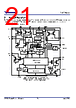
22 / 62 page  P9415-R Datasheet © 2021 Renesas Electronics Corporation 22 May 4, 2021 8.1 Overview The simplified internal block diagram of the P9415-R is shown in Figure 15. External Rx coil(s) and CS capacitor(s) as shown in Figure 1 transfer energy wirelessly using the P9415-R AC1 and AC2 pins to be full-wave-rectified (AC-to-DC). The wireless power is stored on a capacitor(s) connected to VRECT. Until the voltage across the VRECT capacitor exceeds the UVLO threshold, the rectification is performed by the body diodes of the Synchronous Full Bridge Rectifier FETs. After the internal biasing circuit is enabled, the Driver and Control block operate the MOSFET switches of the rectifier in various modes to maintain reliable connections at optimal efficiency. An internal ADC monitors the voltage at VRECT and the load current, the P9415-R sends instructions to the wireless power transmitter to increase or decrease the amount of power transferred or to terminate power transmission based on these readings. The voltage at the output of the P9415-R Main Low-Drop-Out (LDO) regulator is programmed up to 20V using I2C commands. The internal temperature is continuously monitored to ensure proper operation. The voltage at VRECT and the current through the rectifier are sampled periodically and digitized by the ADC. The digital equivalents of the voltage and current are supplied to the internal control logic, which decides whether the loading conditions on VRECT indicate that a change in the operating point is required. If the load is heavy enough to bring the voltage at VRECT below its target, the transmitter is instructed to move its frequency lower, closer to resonance. If the voltage at VRECT is higher than its target, the transmitter is instructed to increase its frequency. To maximize efficiency, the voltage at VRECT is programmed to decrease as the LDO’s load current increases. 8.2 WPC Mode Characteristics 8.2.1 Startup When a mobile device containing the P9415-R is placed on a WPC “Qi” charging pad, it responds to the transmitter’s “ping” signal by rectifying the AC power from the transmitter and storing it on a capacitor connected to VRECT. During the "Ping" phase, once the rectifier voltage at the VRECT pin goes above the UVLO threshold, the digital section of the P9415-R enables communication. The control loop of the P9415-R adjusts the rectifier voltage by sending error packets to the transmitter before and after it enables the VOUT LDO. The VOUT LDO is enabled when the power transfer mode is initiated and the voltage at VRECT, the output of the full-wave synchronous rectifier reaches the target voltage that includes headroom in addition to the LDO VOUT target voltage. For example, if the VOUT voltage target is 12V, the target VRECT voltage is VOUT + headroom, where the headroom is a function of the output current. 8.2.2 Power Transfer Once the “identification and configuration” phase is completed and successful “negotiation and calibration” is made, then the transmitter initiates power transfer mode. The P9415-R control circuit measures the rectifier voltage and sends error packets to the transmitter to adjust the rectifier voltage to the level required to maximize the efficiency of the main LDO linear regulator and to notify the Tx of the current Rectified Power Packet for Foreign Object Detection (FOD) to guarantee safe efficient power transfer. The P9415-R is compatible with the WPC 1.2.4 Specification, and can use compatible Rx coils. Each receiver coil type has a unique inductance value. As such, a unique resonant capacitor (CS) is used for a given type of receiver coil. 8.2.3 Advanced Foreign Object Detection (FOD) WPC MODE When metallic objects are exposed to an alternating magnetic field, eddy currents cause such objects to heat up. Examples of parasitic metal objects are coins, keys, paperclips, etc. The amount of heating depends on the amplitude and frequency of the magnetic field coupled, as well as on the characteristics of the object such as its resistivity, size, and shape. In a wireless power transfer system, the heating manifests itself as a power loss, and therefore a reduced power transfer efficiency. Moreover, if no appropriate measures are taken, the heating could lead to unsafe situations if the objects reach high temperatures. WPC power transmitters and receivers also need to compensate for the power loss due to parasitic metals intentionally designed into the final product: i.e., metals that are neither part of the power transmitter, nor of the power receiver, but which absorb power from magnetic field coupling during power transfer, such as Li-ion batteries, metallic cases, etc. |
|
链接网址 |
| ALLDATASHEET是否为您带来帮助? [ DONATE ] |
关于 Alldatasheet | 广告服务 | 联系我们 | 隐私政策 | 数据表链接 | 链接交换 | 制造商名单 All Rights Reserved©Alldatasheet.com |
| Russian : Alldatasheetru.com | Korean : Alldatasheet.co.kr | Spanish : Alldatasheet.es | French : Alldatasheet.fr | Italian : Alldatasheetit.com Portuguese : Alldatasheetpt.com | Polish : Alldatasheet.pl | Vietnamese : Alldatasheet.vn Indian : Alldatasheet.in | Mexican : Alldatasheet.com.mx | British : Alldatasheet.co.uk | New Zealand : Alldatasheet.co.nz |
|
Family Site : ic2ic.com |
icmetro.com |
 Chinese ▼
 English
 Chinese
 German
 Japanese
 Russian
 Korean
 Spanish
 French
 Italian
 Portuguese
 Polish
 Vietnamese
 Indian
 Mexican
 British
 New Zealand