|
数据搜索系统,热门电子元器件搜索 |
|
|
数据搜索系统,热门电子元器件搜索 |
|
STV-6410-R01 数据表(PDF) 61 Page - STMicroelectronics |
|
|
|||||||||||||||||||||||||||||
STV-6410-R01 数据表(HTML) 61 Page - STMicroelectronics |
|
|
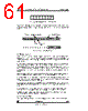
61 / 105 page  CMOS Sensor; Customer Datasheet, Rev 3.0, 28 September 2000 VV5410 & VV6410 Commercial in confidence 61/105 cd5410-6410f-3-0.fm The byte following the address byte contains the address of the first data byte (also referred to as the index). The serial interface can address up to 128, byte registers. If the msb of the second byte is set the automatic increment feature of the address index is selected. 9.4 Message Interpretation All serial interface communications with the sensor must begin with a start condition. If the start condition is followed by a valid address byte then further communications can take place. The sensor will acknowledge the receipt of a valid address by driving the sda wire low. The state of the read/~write bit (lsb of the address byte) is stored and the next byte of data, sampled from sda, can be interpreted. During a write sequence the second byte received is an address index and is used to point to one of the internal registers. The msbit of the following byte is the index auto increment flag. If this flag is set then the serial interface will automatically increment the index address by one location after each slave acknowledge. The master can therefore send data bytes continuously to the slave until the slave fails to provide an acknowledge or the master terminates the write communication with a stop condition or sends a repeated start, (Sr). If the auto increment feature is used the master does not have to send indexes to accompany the data bytes. As data is received by the slave it is written bit by bit to a serial/parallel register. After each data byte has been received by the slave, an acknowledge is generated, the data is then stored in the internal register addressed by the current index. During a read message, the current index is read out in the byte following the device address byte. The next byte read from the slave device are the contents of the register addressed by the current index. The contents of this register are then parallel loaded into the serial/parallel register and clocked out of the device by scl. At the end of each byte, in both read and write message sequences, an acknowledge is issued by the receiving device. Although VV5410/VV6410 is always considered to be a slave device, it acts as a transmitter when the bus master requests a read from the sensor. At the end of a sequence of incremental reads or writes, the terminal index value in the register will be one greater the last location read from or written to. A subsequent read will use this index to begin retrieving data from the internal registers. A message can only be terminated by the bus master, either by issuing a stop condition, a repeated start condition or by a negative acknowledge after reading a complete byte during a read operation. 9.5 The Programmers Model There may be up to 128, 8-bit registers within the camera, accessible by the user via the serial interface. They are grouped 0 0 1 0 0 0 0 Figure 36 : VV5410/VV6410’s Serial Interface Address R/W S address[7:1] R/ W bit A DATA[7:0] A Sensor acknowledges valid address Acknowledge from slave INDEX[6:0] INC P A A DATA[7:0] [0] address Auto increment Index bit Figure 37 : Serial Interface Data Format |
|
链接网址 |
| ALLDATASHEET是否为您带来帮助? [ DONATE ] |
关于 Alldatasheet | 广告服务 | 联系我们 | 隐私政策 | 数据表链接 | 链接交换 | 制造商名单 All Rights Reserved©Alldatasheet.com |
| Russian : Alldatasheetru.com | Korean : Alldatasheet.co.kr | Spanish : Alldatasheet.es | French : Alldatasheet.fr | Italian : Alldatasheetit.com Portuguese : Alldatasheetpt.com | Polish : Alldatasheet.pl | Vietnamese : Alldatasheet.vn Indian : Alldatasheet.in | Mexican : Alldatasheet.com.mx | British : Alldatasheet.co.uk | New Zealand : Alldatasheet.co.nz |
|
Family Site : ic2ic.com |
icmetro.com |
 Chinese ▼
 English
 Chinese
 German
 Japanese
 Russian
 Korean
 Spanish
 French
 Italian
 Portuguese
 Polish
 Vietnamese
 Indian
 Mexican
 British
 New Zealand