|
数据搜索系统,热门电子元器件搜索 |
|
|
数据搜索系统,热门电子元器件搜索 |
|
STV-6410-R01 数据表(PDF) 48 Page - STMicroelectronics |
|
|
|||||||||||||||||||||||||||||
STV-6410-R01 数据表(HTML) 48 Page - STMicroelectronics |
|
|
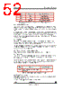
48 / 105 page  VV5410 & VV6410 Digital Video Interface Format cd5410-6410f-3-0.fm Commercial in confidence 48/105 8.3.4 Valid video line timing All valid video data is contained on active video lines. The pixel data appears as a continuous stream of bytes within the active lines. The pixel data may be separated from the line header and end-of-line control sequence by a number of ‘blank’ bytes (07H). 8.3.5 Start of frame line timing The start of frame line which begins each video field contains no video data but instead contains the contents of the serial interface register map. Immediately following the SAV sequence there are 2 padding pixels, (see Figure 27), output as blanking levels, (07H). There will be more blanking codes output after all the serial interface registers have been output . The padding pixels continue to be output until terminated by an end-of-line control sequence. To ensure that no escape/sync characters, (the reserved FF,FF,00 sequence), appear in the sensor status/configuration information the code 07H is output after each serial interface value. If a serial interface register location is unused then a default value, the DeviceH register, is output. The read-out order of the registers is independent of whether the pixel read-out order is shuffled or un-shuffled. 8.3.6 End of frame line timing The end of frame line contains no video data. Its sole purpose is to indicate the end of a frame. 8.4 Detection of sensor using data bus state On power-up a sensor will pull all data lines high and these lines will remain high while the device is in the power up default, low power state. The device is removed from this low power mode by the I2C host writing to sensor register, setup0 [address 1016]. When the device exits the low power mode it will follow a defined power up sequence, please see Figure 30 for more details. Upon completion of the power up sequence the sensor will begin streaming video. 8.5 Resetting the Sensor Via the Serial Interface Bit 2 of setup0 register allows the VV5500/VV6500 sensor to be reset to its power-on state via the serial interface. Setting this “Soft Reset” bit causes all of the serial interface registers including the “Soft Reset” bit to be reset to their default values. This “Soft Reset” leaves the sensor in low-power mode. 8.6 Resetting the Sensor Via the RESETB pin On power-up the RESETB pin is configured as an active low system reset which has the same effect as a soft reset issued via the serial interface as described above. 8.7 Resynchronising the Sensor Via the RESETB pin configured as SINB Bit 5 of the pin mapping register [21] allows the RESETB pin to be re-configured as an active low (edge triggered) system synchronisation signal which will reset the video timing to the beginning of a field but will NOT reset the serial registers therefore the host does not have to reconfigure the sensor following a resynchronisation. |
|
链接网址 |
| ALLDATASHEET是否为您带来帮助? [ DONATE ] |
关于 Alldatasheet | 广告服务 | 联系我们 | 隐私政策 | 数据表链接 | 链接交换 | 制造商名单 All Rights Reserved©Alldatasheet.com |
| Russian : Alldatasheetru.com | Korean : Alldatasheet.co.kr | Spanish : Alldatasheet.es | French : Alldatasheet.fr | Italian : Alldatasheetit.com Portuguese : Alldatasheetpt.com | Polish : Alldatasheet.pl | Vietnamese : Alldatasheet.vn Indian : Alldatasheet.in | Mexican : Alldatasheet.com.mx | British : Alldatasheet.co.uk | New Zealand : Alldatasheet.co.nz |
|
Family Site : ic2ic.com |
icmetro.com |
 Chinese ▼
 English
 Chinese
 German
 Japanese
 Russian
 Korean
 Spanish
 French
 Italian
 Portuguese
 Polish
 Vietnamese
 Indian
 Mexican
 British
 New Zealand