|
数据搜索系统,热门电子元器件搜索 |
|
|
数据搜索系统,热门电子元器件搜索 |
|
STV-6410-R01 数据表(PDF) 62 Page - STMicroelectronics |
|
|
|||||||||||||||||||||||||||||
STV-6410-R01 数据表(HTML) 62 Page - STMicroelectronics |
|
|
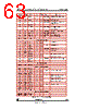
62 / 105 page  VV5410 & VV6410 Serial Control Bus cd5410-6410f-3-0.fm Commercial in confidence 62/105 according to function with each group occupying a 16-byte page of the location address space. There may be up to eight such groups, although this scheme is purely a conceptual feature and not related to the actual hardware implementation, The primary categories are given below: • Status Registers (Read Only). • Setup registers with bit significant functions. • Exposure parameters that influence output image brightness. • System functions and analog test bit significant registers. Any internal register that can be written to can also be read from. There are a number of read only registers that contain device status information, (e.g. design revision details). Names that end with H or L denote the most or least significant part of the internal register. Note that unused locations in the H byte are packed with zeroes. STMicroelectronics sensors that include a 2-wire serial interface are designed with a common address space. If a register parameter is unused in a design, but has been allocated an address in the generic design model, the location is referred to as reserved. If the user attempts to read from any of these reserved or unused locations a default byte will be read back. In VV5410/VV6410 this data is 19H. A write instruction to a reserved (but unused) location is illegal and would not be successful as the device would not allocate an internal register to the data word contained in the instruction. A detailed description of each register follows. The address indexes are shown as decimal numbers in brackets [....] and are expressed in decimal and hexadecimal respectively. Index10 Index16 Name Length R/W Default Comments Status Registers - [0-15] 0 0 deviceH 8 RO 0001_10012 Chip identification number including revision indicator 1 1 deviceL 8 RO 1010_00002 2 2 status0 8 RO 0001_00002 User can determine whether timed serial interface data has been consumed by interrogating flag states 3 3 line_countH 8 RO n/a Current line counter value 4 4 line_countL 8 RO n/a 5 5 xendH 1 RO 359 End x coordinate of image size 6 6 xendL 8 RO 7 7 yendH 1 RO 293 End y coordinate of image size 8 8 yendL 8 RO 9 9 dark_avgH 4 RO 0 This is the average pixel value returned from the dark line offset cancellation algorithm (2’s complement notation) 10 A dark_avgL 8 RO 0 11 B black_avgH 4 RO 0 This is the average pixel value returned from the black line offset cancellation algorithm (2’s complement notation) 12 C black_avgL 8 RO 0 13 D status1 2 RO 00 Flags to indicate whether the x or y image coordinates have been clipped 14-15 E-F unused Setup Registers - [16-31] Table 19 : Serial Interface Address Map. |
|
链接网址 |
| ALLDATASHEET是否为您带来帮助? [ DONATE ] |
关于 Alldatasheet | 广告服务 | 联系我们 | 隐私政策 | 数据表链接 | 链接交换 | 制造商名单 All Rights Reserved©Alldatasheet.com |
| Russian : Alldatasheetru.com | Korean : Alldatasheet.co.kr | Spanish : Alldatasheet.es | French : Alldatasheet.fr | Italian : Alldatasheetit.com Portuguese : Alldatasheetpt.com | Polish : Alldatasheet.pl | Vietnamese : Alldatasheet.vn Indian : Alldatasheet.in | Mexican : Alldatasheet.com.mx | British : Alldatasheet.co.uk | New Zealand : Alldatasheet.co.nz |
|
Family Site : ic2ic.com |
icmetro.com |
 Chinese ▼
 English
 Chinese
 German
 Japanese
 Russian
 Korean
 Spanish
 French
 Italian
 Portuguese
 Polish
 Vietnamese
 Indian
 Mexican
 British
 New Zealand