|
数据搜索系统,热门电子元器件搜索 |
|
|
数据搜索系统,热门电子元器件搜索 |
|
STV-6410-R01 数据表(PDF) 28 Page - STMicroelectronics |
|
|
|||||||||||||||||||||||||||||
STV-6410-R01 数据表(HTML) 28 Page - STMicroelectronics |
|
|
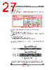
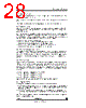
28 / 105 page  VV5410 & VV6410 Digital Video Interface Format cd5410-6410f-3-0.fm Commercial in confidence 28/105 5-wire mode data is output on D[4:0]. Multiplexed with the sampled pixel data is control information including both video timing references, sensor status/configuration data and the pixel average from the current line. Video timing reference information takes the form of field start characters, line start characters, end of line characters and a line counter. Where hexadecimal values are used, they are indicated by a subscript H, such as FFH; other values are decimal. 8.2 Embedded control data To distinguish the control data from the sampled video data all control data is encapsulated in embedded control sequences. These are 6 bytes long and include a combined escape/sync character sequence, 1 control byte (the ‘command byte’) and 2 bytes of supplementary data. To minimise the susceptibility of the embedded control data to random bit errors redundant coding techniques have been used to allow single bit errors in the embedded control words to be corrected. However, more serious corruption of control words or the corruption of escape/sync characters cannot be tolerated without loss of sync to the data stream. To ensure that a loss of sync is detected a simple set of rules has been devised. The four exceptions to the rules are outlined below: 1. Data containing a command word that has two bit errors. 2. Data containing two ‘end of line’ codes that are not separated by a ‘start of line’ code. 3. Data preceding an ‘end of field’ code before a start of frame’ code has been received. 4. Data containing line that do not have sequential line numbers (excluding the ‘end of field’ line). If the host detects one of these violations then it should abandon the current field of video 8.2.1 The combined escape and sync character Each embedded control sequence begins with a combined escape and sync character that is made up of three words. The first two of these are FFH FFH- constituting two words that are illegal in normal data. The next word is 00H - guaranteeing a clear signal transition that allows a host to determine the position of the word boundaries in the serial stream of nibbles. Combined escape and sync characters are always followed by a command byte - making up the four byte minimum embedded control sequence. 8.2.2 The command word The byte that follows the combined escape/sync characters defines the type of embedded control data. Three of the 8 bits are used to carry the control information, four are ‘parity bits’ that allow the host to detect and correct a certain level of errors in the transmission of the command words, the remaining bit is always set to 1 to ensure that the command word never has the value 00H. The coding scheme used allows the correction of single bit errors (in the 8-bit sequence) and the detection of 2 bit errors The three data bits of the command word are interpreted as shown in Figure 13.The even parity bits are based on the following relationships: 1. An even number of ones in the 4-bit sequence (C2, C1, C0 and P0). 2. An even number of ones in the 3-bit sequence (C2, C1, P1). 3. An even number of ones in the 3-bit sequence (C2, C0, P2). 4. An even number of ones in the 3-bit sequence (C1, C0, P3). Table 13 shows how the parity bits maybe used to detect and correct 1-bit errors and detect 2-bit errors. 8.2.3 Supplementary Data The last 2 bytes of the embedded control sequence contains supplementary data. The are two options: 1. The last 2 bytes of the SAV 6 byte sequence contain the current 12-bit line number. The 12-bit line number is packaged up by splitting it into two 6-bit values. Each 6-bit value is then converted into an 8-bit value by adding a zero to the start and an odd word parity bit at the end. 2. The 5th byte of the EAV sequence contains a pixel average for that line either based upon the middle 256 pixels if the CIF,PAL or NTSC video modes are selected or the middle 128 pixels if the QCIF video mode is selected. The final byte is FFH. Note: in 5-wire mode, the embedded control data is calculated as detailed above and output as the most significant 8-bits. The least significant 2-bits are padded with zero. |
|
链接网址 |
| ALLDATASHEET是否为您带来帮助? [ DONATE ] |
关于 Alldatasheet | 广告服务 | 联系我们 | 隐私政策 | 数据表链接 | 链接交换 | 制造商名单 All Rights Reserved©Alldatasheet.com |
| Russian : Alldatasheetru.com | Korean : Alldatasheet.co.kr | Spanish : Alldatasheet.es | French : Alldatasheet.fr | Italian : Alldatasheetit.com Portuguese : Alldatasheetpt.com | Polish : Alldatasheet.pl | Vietnamese : Alldatasheet.vn Indian : Alldatasheet.in | Mexican : Alldatasheet.com.mx | British : Alldatasheet.co.uk | New Zealand : Alldatasheet.co.nz |
|
Family Site : ic2ic.com |
icmetro.com |
 Chinese ▼
 English
 Chinese
 German
 Japanese
 Russian
 Korean
 Spanish
 French
 Italian
 Portuguese
 Polish
 Vietnamese
 Indian
 Mexican
 British
 New Zealand