|
数据搜索系统,热门电子元器件搜索 |
|
|
数据搜索系统,热门电子元器件搜索 |
|
STV-6410-R01 数据表(PDF) 89 Page - STMicroelectronics |
|
|
|||||||||||||||||||||||||||||
STV-6410-R01 数据表(HTML) 89 Page - STMicroelectronics |
|
|
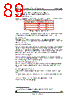
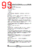
89 / 105 page  CMOS Sensor; Customer Datasheet, Rev 3.0, 28 September 2000 VV5410 & VV6410 Commercial in confidence 89/105 cd5410-6410f-3-0.fm 11.1.4 Audio Amplifier Bandwidth1 The audio circuit can be bandwidth limited to a first order, through the use of minimum external circuitry. The two outputs, AoutP and AoutN, require compensation capacitors that may also be used to define the bandwidth of the circuit. In addition, the inclusion of a resistor (microphone biasing) and decoupling capacitor at the input allows a first order high pass filter to be realised. This can easily be designed to remove frequencies below 50Hz/60Hz (mains electricity noise). 11.2 Voltage Regulators VV5410/VV6410 contains three on-chip voltage regulators, two of which are capable of being powered-down via the serial interface. The third regulator, controlling the band gap references is never powered down. The band gap circuitry is extremely low power consuming only 30 µA. 11.2.1 Regulator for Digital System The output of the regulator, Reg3V3, powers the digital logic and can power an external co-processor. The regulator is powered up by default. The regulator has its own discrete power supply and can source a load of 300 µA -> 150mA and will regulate to 3.0V 10% from an input range of 4-6V. When VV5410/VV6410 is in the USB compatible suspend mode, the clocks to the digital logic are removed to limit power consumption to approximately 80 µA. If an external 3.3V supply is available, this regulator may be overdriven by an external 3.3V supply to directly power the logic. This voltage regulator is never powered down. 11.2.2 Regulator for Audio Amplifier The output of the regulator for the audio amplifier, Aud3V3, drives the load resistor for the microphone and the audio pre- amplifier. As this regulator is capable of being powered-down via the serial interface, all control signals from the digital logic are low during low power/standby. This regulator will be powered up by default. 11.2.3 Regulator for Video Supply/Analogue Core The output of the regulator for the video supply,Vid3V3, powers the analog core. This regulator is capable of being powered- down via the serial interface but will be powered up by default. Note that the sensor will be in low power mode initially and therefore 11.3 Valid Supply Voltage Configurations The power supplies to the VV5410 and VV6410 sensors can be configured such that the sensor will operate in a number of systems: • USB system (sensor will regulate the nominal 5V supply to 3V3 internally) with optional BJT to provide power for a companion chip. • Direct drive the sensor with 3V3 (internal voltage regulators will be powered down in this mode). The next 2figures will detail the options described above: 2. Minimum dynamic range includes dcout (i.e. Vclip- OUT_DC is greater than Vppmin/2) 3. Assumes 10 µF bypass capacitors on all supplies and well separated supplies and grounds 1. Each audio output must have a capacitor (Ccomp) connected to ground to avoid any oscillation Compensation Capacitor (nF) 3dB Bandwidth Units 1 175 kHz 10 41 kHz 100 4.2 kHz Table 62 : Compensation capacitor values |
|
链接网址 |
| ALLDATASHEET是否为您带来帮助? [ DONATE ] |
关于 Alldatasheet | 广告服务 | 联系我们 | 隐私政策 | 数据表链接 | 链接交换 | 制造商名单 All Rights Reserved©Alldatasheet.com |
| Russian : Alldatasheetru.com | Korean : Alldatasheet.co.kr | Spanish : Alldatasheet.es | French : Alldatasheet.fr | Italian : Alldatasheetit.com Portuguese : Alldatasheetpt.com | Polish : Alldatasheet.pl | Vietnamese : Alldatasheet.vn Indian : Alldatasheet.in | Mexican : Alldatasheet.com.mx | British : Alldatasheet.co.uk | New Zealand : Alldatasheet.co.nz |
|
Family Site : ic2ic.com |
icmetro.com |
 Chinese ▼
 English
 Chinese
 German
 Japanese
 Russian
 Korean
 Spanish
 French
 Italian
 Portuguese
 Polish
 Vietnamese
 Indian
 Mexican
 British
 New Zealand