|
数据搜索系统,热门电子元器件搜索 |
|
|
数据搜索系统,热门电子元器件搜索 |
|
SSM2602CPZ-R2 数据表(PDF) 12 Page - Analog Devices |
|
|
|||||||||||||||||||||||||||||
SSM2602CPZ-R2 数据表(HTML) 12 Page - Analog Devices |
|
|
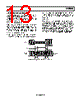
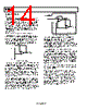
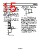
12 / 32 page  SSM2602 Rev. 0 | Page 12 of 32 THEORY OF OPERATION DIGITAL CORE Inside the SSM2602 digital core is one central clock source, called the master clock (MCLK), that produces a reference clock for all internal audio data processing and synchronization. When using an external clock source to drive the MCLK pin, great care should be taken to select a clock source with less than 50 ps of jitter. Without careful generation of the MCLK signal, the digital audio quality will most likely suffer. To enable the SSM2602 to generate the central reference clock in a system, connect a crystal oscillator between the MCLK/XTI input pin and the XTO output pin. To allow an external device to generate the central reference clock, apply the external clock signal directly through the MCLK/XTI input pin. In this configuration, the oscillator circuit of the SSM2602 can be powered down by using the OSC bit (Register R6, Bit D5) to reduce power consumption. To accommodate applications with very high frequency master clocks, the internal core reference clock of the SSM2602 can be set to either MCLK or MCLK divided by 2. This is enabled by adjusting the setting of the CLKDIV2 bit (Register R8, Bit D6). Complementary to this feature, the CLKOUT pin can also drive external clock sources with either the core clock signal or core clock divided by 2 by enabling the CLKODIV2 bit (Register R8, Bit D7). ADC AND DAC The SSM2602 contains a pair of oversampling Σ-Δ ADCs. The maximum ADC full-scale input level is 1.0 V rms when AVDD = 3.3 V. If the input signal to the ADC exceeds this level, data overloading occurs and causes audible distortion. The ADC can accept analog audio input from either the stereo line inputs or the monaural microphone input. Note that the ADC can only accept input from a single source, so the user must choose either the line inputs or the microphone input as the source using the INSEL bit (Register R4, Bit D2). The digital data from the ADC output, once converted, is processed using the ADC filters. Complementary to the ADC channels, the SSM2602 contains a pair of oversampling Σ-Δ DACs that convert the digital audio data from the internal DAC filters into an analog audio signal. The DAC output can also be muted by setting the DACMU bit (Register R5, Bit D3) in the control register. ADC HIGH-PASS AND DAC DE-EMPHASIS FILTERS The ADC and DAC employ separate digital filters that perform 24-bit signal processing. The digital filters are used for both record and playback modes and are optimized for each individual sampling rate used. For recording mode operations, the unprocessed data from the ADC enters the ADC filters and is converted to the appropriate sampling frequency, and then is output to the digital audio interface. For playback mode operations, the DAC filters convert the digital audio interface data to oversampled data, using a sampling rate selected by the user. The oversampled data is processed by the DAC and then is sent to the analog output mixer by enabling the DACSEL (Register R4, Bit D4). Users have the option of setting up the device so that any dc offset in the input source signal is automatically detected and removed. To accomplish this, enable the digital high-pass filter (see Table 2 for characteristics) contained in the ADC digital filters by using the ADCHPF bit (Register R5, Bit D0). In addition, users can implement digital de-emphasis by using the DEEMPH bits (Register R5, Bit D1 and Bit D2). |
|
链接网址 |
| ALLDATASHEET是否为您带来帮助? [ DONATE ] |
关于 Alldatasheet | 广告服务 | 联系我们 | 隐私政策 | 数据表链接 | 链接交换 | 制造商名单 All Rights Reserved©Alldatasheet.com |
| Russian : Alldatasheetru.com | Korean : Alldatasheet.co.kr | Spanish : Alldatasheet.es | French : Alldatasheet.fr | Italian : Alldatasheetit.com Portuguese : Alldatasheetpt.com | Polish : Alldatasheet.pl | Vietnamese : Alldatasheet.vn Indian : Alldatasheet.in | Mexican : Alldatasheet.com.mx | British : Alldatasheet.co.uk | New Zealand : Alldatasheet.co.nz |
|
Family Site : ic2ic.com |
icmetro.com |
 Chinese ▼
 English
 Chinese
 German
 Japanese
 Russian
 Korean
 Spanish
 French
 Italian
 Portuguese
 Polish
 Vietnamese
 Indian
 Mexican
 British
 New Zealand