|
数据搜索系统,热门电子元器件搜索 |
|
|
数据搜索系统,热门电子元器件搜索 |
|
SSM2602CPZ-R2 数据表(PDF) 16 Page - Analog Devices |
|
|
|||||||||||||||||||||||||||||
SSM2602CPZ-R2 数据表(HTML) 16 Page - Analog Devices |
|
|
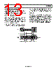
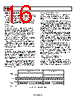
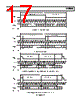
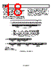
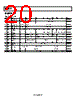
16 / 32 page  SSM2602 Rev. 0 | Page 16 of 32 DIGITAL AUDIO INTERFACE The digital audio input can support the following four digital audio communication protocols: right-justified mode, left-justified mode, I2S mode, and digital-signal processor (DSP) mode. The mode selection is performed by writing to the FORMAT bits of the digital audio interface register (Register R7, Bit D1 and Bit D0). All modes are MSB first and operate with data of 16 to 32 bits. Recording Mode On the RECDAT output pin, the digital audio interface can send digital audio data for recording mode operation. The digital audio interface outputs the processed internal ADC digital filter data onto the RECDAT output. The digital audio data stream on RECDAT comprises left- and right-channel audio data that is time domain multiplexed. The RECLRC is the digital audio frame clock signal that separates left- and right-channel data on the RECDAT lines. The BCLK signal acts as the digital audio clock. Depending on if the SSM2602 is in master or slave mode, the BCLK signal is either an input or an output signal. During a recording operation, RECDAT and RECLRC must be synchronous to the BCLK signal to avoid data corruption. Playback Mode On the PBDAT input pin, the digital audio interface can receive digital audio data for playback mode operation. The digital audio data stream on PBDAT comprises left- and right-channel audio data that is time domain multiplexed. The PBLRC is the digital audio frame clock signal that separates left- and right-channel data on the PBDAT lines. The BCLK signal acts as the digital audio clock. Depending on if the SSM2602 is in master or slave mode, the BCLK signal is either an input or an output signal. During a playback operation, PBDAT and PBLRC must be synchronous to the BCLK signal to avoid data corruption. Digital Audio Data Sampling Rate To accommodate a wide variety of commonly used DAC and ADC sampling rates, the SSM2602 allows for two modes of operation, normal and USB, selected by the USB bit (Register R8, Bit D0). In normal mode, the SSM2602 supports digital audio sampling rates from 8 kHz to 96 kHz. Normal mode supports 256 fS and 384 fS based clocks. To select the desired sampling rate, the user must set the appropriate sampling rate register in the SR control bits (Register R8, Bit D2 to Bit D5) and match this selection to the core clock frequency that is pulsed on the MCLK pin. See Table 30 and Table 31 for guidelines. In USB mode, the SSM2602 supports digital audio sampling rates from 8 kHz to 96 kHz. USB mode is enabled on the SSM2602 to support the common universal serial bus (USB) clock rate of 12 MHz, or to support 24 MHz if the CLKDIV2 control register bit is activated. The user must set the appropriate sampling rate in the SR control bits (Register R8, Bit D2 to Bit D5). See Table 30 and Table 31 for guidelines. Note that the sampling rate is generated as a fixed divider from the MCLK signal. Because all audio processing references the core MCLK signal, corruption of this signal, in turn, corrupts the outgoing audio quality of the SSM2602. The BCLK/RECLRC/ RECDAT or BCLK/PBLRC/PBDAT signals must be synchronized with MCLK in the digital audio interface circuit. MCLK must be faster or equal to the BCLK frequency to guarantee that no data is lost during data synchronization. The BCLK frequency should be greater than Sampling Rate × Word Length × 2 Ensuring that the BCLK frequency is greater than this value guarantees that all valid data bits are captured by the digital audio interface circuitry. For example, if a 32 kHz digital audio sampling rate with a 32-bit word length is desired, BCLK ≥ 2.048 MHz. RECLRC/ PBLRC BCLK RECDAT/ PBDAT 12 34 N X X X X N 1 2 LEFT CHANNEL 3 RIGHT CHANNEL 1/ fS X = DON’T CARE. Figure 23. Left-Justified Audio Input Mode |
|
链接网址 |
| ALLDATASHEET是否为您带来帮助? [ DONATE ] |
关于 Alldatasheet | 广告服务 | 联系我们 | 隐私政策 | 数据表链接 | 链接交换 | 制造商名单 All Rights Reserved©Alldatasheet.com |
| Russian : Alldatasheetru.com | Korean : Alldatasheet.co.kr | Spanish : Alldatasheet.es | French : Alldatasheet.fr | Italian : Alldatasheetit.com Portuguese : Alldatasheetpt.com | Polish : Alldatasheet.pl | Vietnamese : Alldatasheet.vn Indian : Alldatasheet.in | Mexican : Alldatasheet.com.mx | British : Alldatasheet.co.uk | New Zealand : Alldatasheet.co.nz |
|
Family Site : ic2ic.com |
icmetro.com |
 Chinese ▼
 English
 Chinese
 German
 Japanese
 Russian
 Korean
 Spanish
 French
 Italian
 Portuguese
 Polish
 Vietnamese
 Indian
 Mexican
 British
 New Zealand