|
数据搜索系统,热门电子元器件搜索 |
|
|
数据搜索系统,热门电子元器件搜索 |
|
MPZ2012S221A 数据表(PDF) 44 Page - STMicroelectronics |
|
|
|||||||||||||||||||||||||||||
MPZ2012S221A 数据表(HTML) 44 Page - STMicroelectronics |
|
|
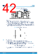
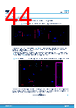
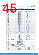
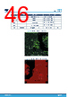
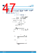
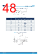
44 / 56 page  11 Application board The application board (STEVAL-L6983IV1) schematic is shown in the figure below. Figure 50. Schematic of the application board (unregulated isolated output) The additional input filter (in the dotted box in Figure 50, on the bottom side of the board) limits the conducted emission on the power supply. In case the filter is not necessary or should be bypassed for any test, two 0 Ω resistors should be placed at Rf1 and Rf2. The isolated output supplied by the board is unregulated. Nevertheless, a post-regulation circuit (see schematic in Figure 51) is provided on the bottom side (components not mounted). The values and the components indicated in the BOM below (Table 9 ) are assumed for a dual voltage 18 V / - 5 V. Figure 51. Proposed circuitry for post-regulation (not mounted, bottom side) for dual voltage (18 V / - 5 V) If a different dual isolated voltage is necessary (for example, 15 V / - 6 V), the replacement of two components is enough to adapt the board: the Zener diode DZ2 (with a diode providing the most suitable Zener voltage) and the resistor divider (one of the two resistors) R1-R2, in accordance with the equation: VISO+=1.2V∙R1+R2R2+VDZ1 (48) L6983I Application board DS14040 - Rev 1 page 44/56 |
|
链接网址 |
| ALLDATASHEET是否为您带来帮助? [ DONATE ] |
关于 Alldatasheet | 广告服务 | 联系我们 | 隐私政策 | 数据表链接 | 链接交换 | 制造商名单 All Rights Reserved©Alldatasheet.com |
| Russian : Alldatasheetru.com | Korean : Alldatasheet.co.kr | Spanish : Alldatasheet.es | French : Alldatasheet.fr | Italian : Alldatasheetit.com Portuguese : Alldatasheetpt.com | Polish : Alldatasheet.pl | Vietnamese : Alldatasheet.vn Indian : Alldatasheet.in | Mexican : Alldatasheet.com.mx | British : Alldatasheet.co.uk | New Zealand : Alldatasheet.co.nz |
|
Family Site : ic2ic.com |
icmetro.com |
 Chinese ▼
 English
 Chinese
 German
 Japanese
 Russian
 Korean
 Spanish
 French
 Italian
 Portuguese
 Polish
 Vietnamese
 Indian
 Mexican
 British
 New Zealand