|
数据搜索系统,热门电子元器件搜索 |
|
|
数据搜索系统,热门电子元器件搜索 |
|
MPZ2012S221A 数据表(PDF) 38 Page - STMicroelectronics |
|
|
|||||||||||||||||||||||||||||
MPZ2012S221A 数据表(HTML) 38 Page - STMicroelectronics |
|
|
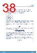
38 / 56 page  10.2 Transformer selection The transformer has two essential tasks: • Providing the isolation between the primary and secondary side in accordance with the application requirements • Generating the necessary secondary output voltage from the regulated primary voltage with the most suitable turn ratio The transformer selection implies the definition of the following parameters: • Isolation voltage • Turn ratio • Primary inductance • Peak and RMS currents • Windings resistance • Leakage inductance • Parasitic capacitances Isolation voltage The isolation of the transformer in terms of voltage capability (1.5 kV, 4 kV, and so on) and type (functional basic, reinforced, etc.) is mainly driven by the application. Both parameters normally affect the size of the transformer as well as other electrical characteristics (for example, winding resistance, leakage inductance, etc.). Turn ratio Naming Npri and Nsec the number of turns of the primary and secondary windings respectively, the turn ratio is so defined: N= NsecNprim (37) Considering Eq. (24), the turn ratio must be defined so that the voltage at the secondary output is the desired one over the whole secondary output current range: N≥ VOUT_sec+Rwind_sec∙IOUT_sec+VFD1 VOUT_pri+IOUTpri∙RDSonLS+Rwind_pri (38) If no current is drawn from the primary output, the turn ratio should only be chosen to compensate the drops due to the secondary winding resistance and the Schottky diode. The effect of the leakage inductance on the secondary output voltage regulation (not included in the equation above) should be taken into account too. Figure 17 clearly shows how the secondary output voltage can drift due to the leakage inductance. Primary inductance The choice of the primary inductance does not differ so much from a standard buck. The magnetizing current, (see Figure 44) which combines the two winding currents, has the same shape as the buck inductor current and can be defined as: IL_mag=Ipri+N∙Isec (39) L6983I Transformer selection DS14040 - Rev 1 page 38/56 |
|
链接网址 |
| ALLDATASHEET是否为您带来帮助? [ DONATE ] |
关于 Alldatasheet | 广告服务 | 联系我们 | 隐私政策 | 数据表链接 | 链接交换 | 制造商名单 All Rights Reserved©Alldatasheet.com |
| Russian : Alldatasheetru.com | Korean : Alldatasheet.co.kr | Spanish : Alldatasheet.es | French : Alldatasheet.fr | Italian : Alldatasheetit.com Portuguese : Alldatasheetpt.com | Polish : Alldatasheet.pl | Vietnamese : Alldatasheet.vn Indian : Alldatasheet.in | Mexican : Alldatasheet.com.mx | British : Alldatasheet.co.uk | New Zealand : Alldatasheet.co.nz |
|
Family Site : ic2ic.com |
icmetro.com |
 Chinese ▼
 English
 Chinese
 German
 Japanese
 Russian
 Korean
 Spanish
 French
 Italian
 Portuguese
 Polish
 Vietnamese
 Indian
 Mexican
 British
 New Zealand