|
数据搜索系统,热门电子元器件搜索 |
|
|
数据搜索系统,热门电子元器件搜索 |
|
300-R010-45G 数据表(PDF) 4 Page - Magnetrol International, Inc. |
|
|
|||||||||||||||||||||||||||||
300-R010-45G 数据表(HTML) 4 Page - Magnetrol International, Inc. |
|
|
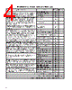
4 / 36 page  4 MEASUREMENT RANGE CALCULATIONS, cont. Operating Parameter Condition Performance Application Multiplier SURFACE AGITATION: Surface agitation or waves can degrade the Smooth, glasslike surface 1.0 performance. Moderate agitation results in only slight degradation Slight agitation, choppiness 0.9 of performance. The worst case is when the surface is a good Heavy agitation 0.8 reflector, but in the wrong direction. (See also transducer alignment.) Slight vortex (6°) 0.7 VAPORS AND STEAM: Vapors in the air space, above the process, become apparent, and cause problems when the liquid process No condensation 1.0 temperature is well above the temperature of the airspace. The greater the difference, the more expected vapor problems. The problems result from condensation or layering in the sound path, both of which attenuate the sound signal, degrading performance. Little condensation 0.9 Avoid steam if possible. To avoid these problems, ensure that the vessel is insulated so that vapors are less likely to condense. If a vent is used, be sure that the Much condensation/ 0.8 vent, which is where condensation will form, is well away from the foggy appearance transducer. BEAM SPREAD INTERFERENCE: It is strongly recommended that No interference 1.0 nothing be allowed within the transducer’s beam, except the liquid which is being monitored. Often, the signal from the liquid will be Agitator at speed less than 60 RPM 1.0 strong, compared to the signal from other sources, such as ladder rungs, filling process material, support struts, etc. For that reason, Agitator at speed greater than 60 RPM Consult some applications may provide satisfactory results, even with Factory interference. Interference from agitator blades is only an intermittent interference that usually has little effect on performance. Interference outside 4°, far from 0.8 It is recommended there be no interference within the 6° half angle transducer (in bottom third of range) of the transducer beam. If interference is unavoidable, make the inter- ference as far as possible from the transducer so that the real signal Interference outside 4°, near to 0.5 at the longest distance is stronger than the interference signal. transducer (in top third of range) TRANSDUCER ALIGNMENT: Optimum performance is obtained when Beam perpendicular to liquid surface 1.0 the transducer is perfectly aligned. If the process is not perpendicular to the sound beam, the sound will not reflect properly back to the transducer. The effect is significant. Beam 4° off from perpendicular 0.5 FOAM: Even small thicknesses of foam can attenuate the ultrasound No foam 1.0 and render the system inoperative. If possible, moving the transducer Light froth, less than 0.25" thick 0.8 to an area in the tank where there is less foam will improve the performance. Thick, heavy-density foams can sometimes produce Light foam, less than 0.5" thick 0.5 a reflection from the top of the foam. The multipliers shown at right Light foam, more than 1" thick 0.1 are general guidelines. For further assistance consult the factory. DUST: Dust attenuates the sound and results in poor performance. No dust 1.0 Even barely perceptible haze in the air can cause significant Haze, barely perceptible 0.7 attenuation. Slight dust 0.4 Heavy dust 0.1 AIR MOVEMENT: The movement of air, as possible in an open top No air movement 1.0 vessel, can create a layer from which the sound will reflect. This will Open vessel, but transducer below rim 0.8 be most noticeable in applications where vapors or steam tend to form. Open air movement in sound path 0.7 AMBIENT TEMPERATURE: The ambient temperature can have a -20° to +140° F (-29° to +50° C) 1.0 significant effect on the sound and on the transducer’s capability to -40° to -20° F (-40° to -29° C) 0.9 transmit and receive sound. The most noticeable effect on the transducer is at the temperature extremes. +140° to +160° F (+50 to +70° C) 0.9 PRESSURE: Sound requires air molecules to be able to travel. Sound -10 to +50 psig (0.689 to +3.45 Bar) 1.0 will not travel in a vacuum. Likewise, higher pressures will allow the sound to continue without decay, which can cause problems with Pressures outside above rating Consult multiple echoes. Factory Multiply all values together in the application column Maximum Potential Range for Model 300/301 X 30' Maximum allowable measurement range for this application |
|
链接网址 |
| ALLDATASHEET是否为您带来帮助? [ DONATE ] |
关于 Alldatasheet | 广告服务 | 联系我们 | 隐私政策 | 数据表链接 | 链接交换 | 制造商名单 All Rights Reserved©Alldatasheet.com |
| Russian : Alldatasheetru.com | Korean : Alldatasheet.co.kr | Spanish : Alldatasheet.es | French : Alldatasheet.fr | Italian : Alldatasheetit.com Portuguese : Alldatasheetpt.com | Polish : Alldatasheet.pl | Vietnamese : Alldatasheet.vn Indian : Alldatasheet.in | Mexican : Alldatasheet.com.mx | British : Alldatasheet.co.uk | New Zealand : Alldatasheet.co.nz |
|
Family Site : ic2ic.com |
icmetro.com |
 Chinese ▼
 English
 Chinese
 German
 Japanese
 Russian
 Korean
 Spanish
 French
 Italian
 Portuguese
 Polish
 Vietnamese
 Indian
 Mexican
 British
 New Zealand