|
数据搜索系统,热门电子元器件搜索 |
|
|
数据搜索系统,热门电子元器件搜索 |
|
804-R010-330 数据表(PDF) 8 Page - Magnetrol International, Inc. |
|
|
|||||||||||||||||||||||||||||
804-R010-330 数据表(HTML) 8 Page - Magnetrol International, Inc. |
|
|
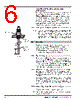
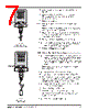
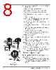
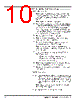
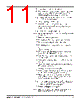
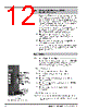
8 / 32 page  50-604 Kotron Model 804 Sentinel II RF Level Transmitter 5 NOTE: Do not allow the probe to fall in the tank while performing steps 7 through 18. 7. Loosen both socket head clamp screws. 8. Pull clamp and Teflon® retaining bushing off probe. 9. While holding the probe cable, loosen upper probe nut. 10. Pull excess cable up, through the probe nuts, until cable is taut. 11. Tighten the probe nuts. 12. Cut off cable 1.35" (34 mm) above top of upper probe nut, and strip off 1.25" (32 mm) of insulation. 13. Slide Teflon retaining bushing onto cable, and seat it into the upper probe nut. 14. Slide clamp onto cable and seat it in the Teflon retaining bushing. 15. Tighten both socket head clamp screws to approximately 35 inches/pound torque. 16. Slip mylar housing insulator over clamp. 17. Screw housing onto probe and tighten. Make sure conduit connection is properly aligned for wire entry. 18. Remove housing cover. NOTE: Refer to Electrostatic Discharge Handling Procedure on page 9. 19. Remove the electronics assembly from the housing by loosening the four mounting screws. 20. Locate the white wire, which is connected to the probe terminal (P) on the circuit board, and connect its free end to the probe connection screw. 21. Reinstall the electronics assembly into the housing. Caution: Check probe terminal connection carefully to ensure that the lug will not short packing gland or interfere with assembly of amplifier housing to probe. 22. Proceed to Wiring section on page 9. 2.2.4 Remote Mount with Standard Rigid Probe 2.2.4.1 Main amplifier Remote amplifier assemblies are normally shipped from the factory assembled into an “L” mounting bracket. To install amplifier assembly, proceed as follows. Refer to Figure 4. Figure 4 Remote Mount with Rigid Probe Wiring – (Black) – (Black) Top view Preamplifier Side view Preamplifier + (Red) Shield connected to green ground screw Probe wire (white) + (Red) Shield connected to green ground screw Side view Main Amplifier Probe wire (white) (Daughter board under shield) |
|
链接网址 |
| ALLDATASHEET是否为您带来帮助? [ DONATE ] |
关于 Alldatasheet | 广告服务 | 联系我们 | 隐私政策 | 数据表链接 | 链接交换 | 制造商名单 All Rights Reserved©Alldatasheet.com |
| Russian : Alldatasheetru.com | Korean : Alldatasheet.co.kr | Spanish : Alldatasheet.es | French : Alldatasheet.fr | Italian : Alldatasheetit.com Portuguese : Alldatasheetpt.com | Polish : Alldatasheet.pl | Vietnamese : Alldatasheet.vn Indian : Alldatasheet.in | Mexican : Alldatasheet.com.mx | British : Alldatasheet.co.uk | New Zealand : Alldatasheet.co.nz |
|
Family Site : ic2ic.com |
icmetro.com |
 Chinese ▼
 English
 Chinese
 German
 Japanese
 Russian
 Korean
 Spanish
 French
 Italian
 Portuguese
 Polish
 Vietnamese
 Indian
 Mexican
 British
 New Zealand