|
数据搜索系统,热门电子元器件搜索 |
|
|
数据搜索系统,热门电子元器件搜索 |
|
804-R010-330 数据表(PDF) 9 Page - Magnetrol International, Inc. |
|
|
|||||||||||||||||||||||||||||
804-R010-330 数据表(HTML) 9 Page - Magnetrol International, Inc. |
|
|
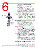
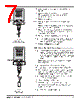
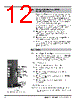
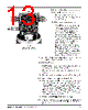
9 / 32 page  50-604 Kotron Model 804 Sentinel II RF Level Transmitter 6 1. Remove amplifier from mounting bracket. 2. Install bracket in a location that is isolated from tempera- tures below -40° F (-40° C) and above +160° F (+70° C) and vibration which could cause mechanical damage. The unit may be mounted up to 2500 feet (760 m) from the probe assembly. Location should also offer easy access for wiring, calibration, and maintenance. 3. Re-install amplifier onto mounting bracket. 4. Remove the electronics assembly from the housing by loos- ening the four mounting screws. 5. Route the twisted shielded pair cable up through the hous- ing base as shown in Figure 4 on page 5. 6. Remove the shield from the electronics assembly by removing the top mounting screw and snapping the shield off of the bracket. 7. Attach the twisted pair to the connection screws on the daughter board (refer to Figure 4 on page 5) as follows: « Red wire to the + (positive) screw terminal; « Black wire to the – (negative) terminal; « Shield to the shield terminal. 8. Dress wires and reassemble shield to the bracket. Reinstall the electronics assembly into the housing base. 9. Replace the housing cover and proceed with the wiring of the preamplifier. 2.2.4.2 Preamplifier 1. Thread probe into mounting bushing on tank. 2. Tighten securely, making certain that the wrench is applied only to the lower probe nut. Refer to Figure 4 on page 5. 3. Screw housing on probe until hand tight. Housing may be wrench tightened to align conduit connection with conduit. 4. Connect the white wire from the remote KISO board to the probe connection screw. 5. Attach the twisted pair to the remote KISO board (refer to Figure 4 on page 5) as follows: « Red wire to the + (positive) terminal of TB2; « Black wire to the – (negative) terminal of TB2; « Shield to the green ground screw, inside of the housing base. 6. Proceed to Wiring section on page 9. Figure 5 Remount Mount with Flexible Probe Wiring – (Black) – (Black) Top view Preamplifier Side view Preamplifier + (Red) Shield connected to green ground screw Probe wire (white) + (Red) Shield connected to green ground screw Side view Main Amplifier Probe wire (white) (Daughter board under shield) |
|
链接网址 |
| ALLDATASHEET是否为您带来帮助? [ DONATE ] |
关于 Alldatasheet | 广告服务 | 联系我们 | 隐私政策 | 数据表链接 | 链接交换 | 制造商名单 All Rights Reserved©Alldatasheet.com |
| Russian : Alldatasheetru.com | Korean : Alldatasheet.co.kr | Spanish : Alldatasheet.es | French : Alldatasheet.fr | Italian : Alldatasheetit.com Portuguese : Alldatasheetpt.com | Polish : Alldatasheet.pl | Vietnamese : Alldatasheet.vn Indian : Alldatasheet.in | Mexican : Alldatasheet.com.mx | British : Alldatasheet.co.uk | New Zealand : Alldatasheet.co.nz |
|
Family Site : ic2ic.com |
icmetro.com |
 Chinese ▼
 English
 Chinese
 German
 Japanese
 Russian
 Korean
 Spanish
 French
 Italian
 Portuguese
 Polish
 Vietnamese
 Indian
 Mexican
 British
 New Zealand