|
数据搜索系统,热门电子元器件搜索 |
|
|
数据搜索系统,热门电子元器件搜索 |
|
804-R010-330 数据表(PDF) 13 Page - Magnetrol International, Inc. |
|
|
|||||||||||||||||||||||||||||
804-R010-330 数据表(HTML) 13 Page - Magnetrol International, Inc. |
|
|
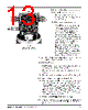
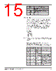
13 / 32 page  Relay 2 (TB3) Relay 1 (TB2) 50-604 Kotron Model 804 Sentinel II RF Level Transmitter 10 2.4.2 Wiring Operation 2.4.2.1 4–20 mA output wiring Connect the positive wire to the + terminal; connect the negative wire to the – terminal. 2.4.2.2 Active or passive selection The 4–20 mA output can be config- ured for active or passive operation. Active mode allows the Sentinel II to drive the loop (for example, the Sentinel II is the 24 VDC power supply). The passive mode allows the Sentinel II to react like a loop-powered transmitter (the loop power is supplied elsewhere). Switch S1 changes the mode. See Figure 6 on page 9. Cable should be shielded, twisted pair, 22 gauge stranded conductors. In the active mode of operation the shield should be grounded at the model 804. In the passive mode the shield should be grounded at the power source. Caution: Applying power to the 4–20 mA output, while in the active mode, will seriously damage the instrument. 2.4.2.3 RS-485 output RS-485 communication is achieved by means of a 2-wire, twisted pair connected to terminal block. 1. Connect the A wire from the control room converter to terminal A. 2. Connect the control room converter wire B to terminal B. NOTE: Polarity among units in loop must be observed. 3. If connecting multiple 804 units in a daisy chain configu- ration, be sure to connect the wiring in parallel and have the ending 804 unit with the termination resistor jumpered. The termination jumper pins are located under the shield, below the RS-485 terminal block. The jumper (JP1) should be in positions 2 and 3, removed on all units except the last one in the chain. The last unit should have the jumper in positions 1 and 2. 4. Proceed to Unit Configuration section on page 11. NOTE: If connecting several units, note the color wire used for A and B; ensure that the same designated color is used for each of the units. NO CO NC NO CO NC NO CO NC NO CO NC Relay 4 (TB4) Relay 3 (TB5) L1 (+) Not used L2/N (–) Input power (TB1) Figure 7 Power Supply Board Terminal Connections |
|
链接网址 |
| ALLDATASHEET是否为您带来帮助? [ DONATE ] |
关于 Alldatasheet | 广告服务 | 联系我们 | 隐私政策 | 数据表链接 | 链接交换 | 制造商名单 All Rights Reserved©Alldatasheet.com |
| Russian : Alldatasheetru.com | Korean : Alldatasheet.co.kr | Spanish : Alldatasheet.es | French : Alldatasheet.fr | Italian : Alldatasheetit.com Portuguese : Alldatasheetpt.com | Polish : Alldatasheet.pl | Vietnamese : Alldatasheet.vn Indian : Alldatasheet.in | Mexican : Alldatasheet.com.mx | British : Alldatasheet.co.uk | New Zealand : Alldatasheet.co.nz |
|
Family Site : ic2ic.com |
icmetro.com |
 Chinese ▼
 English
 Chinese
 German
 Japanese
 Russian
 Korean
 Spanish
 French
 Italian
 Portuguese
 Polish
 Vietnamese
 Indian
 Mexican
 British
 New Zealand