|
数据搜索系统,热门电子元器件搜索 |
|
|
数据搜索系统,热门电子元器件搜索 |
|
804-R010-330 数据表(PDF) 12 Page - Magnetrol International, Inc. |
|
|
|||||||||||||||||||||||||||||
804-R010-330 数据表(HTML) 12 Page - Magnetrol International, Inc. |
|
|
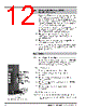
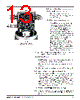
12 / 32 page  50-604 Kotron Model 804 Sentinel II RF Level Transmitter 9 2.3 Electrostatic Discharge (ESD) Handling Procedure Magnetrol/STIs electronic instruments are manufactured to the highest quality standards. These instruments utilize electronic components which may be damaged by static electricity present in most work environments. The follow- ing steps are recommended to reduce the risk of compo- nent failure due to electrostatic discharge: 1. Ship and store circuit boards in anti-static bags. If an anti- static bag is not available, wrap board in aluminum foil. Do not place boards on foam packing materials. 2. Use a grounding wrist strap when installing and removing circuit boards. A grounded workstation is also recommended. 3. Handle printed circuit boards only by the edges. Do not touch components or connector pins. 4. Ensure that all electrical connections are completely made and none are partial or floating. Ground all equipment to a good, earth ground. 2.4 Wiring 2.4.1 Wiring Power Supply Board For connection of power and control circuit, 16–22 AWG stranded wire is acceptable. Refer to Figures 6 and 7 for power supply board layout and terminal locations. 2.4.1.1 Power wiring 1. Ensure that power source is turned off from unit. 2. Pull the power supply wires through the conduit connection. 3. Connect the positive (hot) supply wire to the L1 on terminal block TB1. 4. Connect the negative (neutral) supply wire to the L2/N on terminal block TB1. 5. Connect the ground wire to the green screw in the housing base. 2.4.1.2 Discrete output wiring NOTES: Output #1 may be used as a dedicated diagnostic alarm. Any or all outputs can be used for LEAD/LAG pump sequencing. Figure 6 Logic Board Terminal Connections 4–20 mA terminals RS-485 terminals Active/Passive switch selectors Passive Manual self-test (+) A B (–) } Active } Remote contact } |
|
链接网址 |
| ALLDATASHEET是否为您带来帮助? [ DONATE ] |
关于 Alldatasheet | 广告服务 | 联系我们 | 隐私政策 | 数据表链接 | 链接交换 | 制造商名单 All Rights Reserved©Alldatasheet.com |
| Russian : Alldatasheetru.com | Korean : Alldatasheet.co.kr | Spanish : Alldatasheet.es | French : Alldatasheet.fr | Italian : Alldatasheetit.com Portuguese : Alldatasheetpt.com | Polish : Alldatasheet.pl | Vietnamese : Alldatasheet.vn Indian : Alldatasheet.in | Mexican : Alldatasheet.com.mx | British : Alldatasheet.co.uk | New Zealand : Alldatasheet.co.nz |
|
Family Site : ic2ic.com |
icmetro.com |
 Chinese ▼
 English
 Chinese
 German
 Japanese
 Russian
 Korean
 Spanish
 French
 Italian
 Portuguese
 Polish
 Vietnamese
 Indian
 Mexican
 British
 New Zealand