|
数据搜索系统,热门电子元器件搜索 |
|
|
数据搜索系统,热门电子元器件搜索 |
|
ANT-2.4-CW-RCL-RPS 数据表(PDF) 27 Page - Microchip Technology |
|
|
|||||||||||||||||||||||||||||
ANT-2.4-CW-RCL-RPS 数据表(HTML) 27 Page - Microchip Technology |
|
|
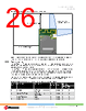
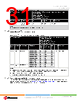
27 / 73 page  WINCS02IC and WINCS02 Family Device Overview Data Sheet © 2024-2025 Microchip Technology Inc. and its subsidiaries DS70005577B - 27 Table 2-5. Approved External Antenna List with Antenna Gain for WINCS02 Module (continued) Antenna No. Part Number Manufacturer Antenna Gain (dBi) Antenna Type Regulatory Certification FCC/ISED(2) (3) CE 5 RFA-02-C2H1-D034 Alead 2 Dipole x x 6 RFA-02-D3 Aristotle 2 Dipole x x 7 RFDPA870920IMLB301 Walsin 1.84 Dipole x x 8 RFDPA870920IMAB302(5) Walsin 1.82 Dipole x x 9 RFDPA870920IMAB305 Walsin 1.82 Dipole x x 10 RFDPA870910IMAB308(5) Walsin 2 Dipole x x 11 RFA-02-C2M2 Aristotle 2 Dipole x x 12 RN-SMA-S-RP(5) Microchip 0.56 Dipole x x 13 W1049B030(5) Pulse 2 Dipole x x 14 RN-SMA4-RP Microchip 2.2 Dipole x x Notes: 1. ‘x’ denotes the antennas covered under the certification. 2. If the end product using the module is designed to have an antenna port that is accessible to the end user, a unique (non-standard) antenna connector (as permissible by FCC) must be used (for example, RP (Reverse Polarity)-SMA socket). 3. If an RF coaxial cable is used between the module RF output and the enclosure, a unique (non-standard) antenna connector must be used in the enclosure wall to interface with the antenna. 4. Contact the antenna vendor for detailed antenna specifications to review the suitability to the end product operating environment and to identify alternatives. 5. If any of these antennas are used, an additional post-calibration step is required on the customer's application board. For more details, refer to the WINCS02 Module External Antenna Calibration Guide (DS50003753). 2.8 WINCS02 Module Reflow Profile Information The WINCS02 Module was assembled using the IPC/JEDEC J-STD-020 standard lead-free reflow profile. The WINCS02 Module can be soldered to the host board using standard leaded or lead-free solder reflow profiles. To avoid damaging the module, adhere to the following recommendations: • For solder reflow recommendations, refer to the AN233 Solder Reflow Recommendation Application Note (DS00233). • Do not exceed a peak temperature (TP) of 250°C. • For specific reflow profile recommendations from the vendor, refer to the Solder Paste Data Sheet. • Use no-clean flux solder paste. • Do not wash as moisture can be trapped under the shield. • Use only one flow. If the PCB requires multiple flows, apply the module on the final flow. 2.8.1 Cleaning The exposed GND pad helps to self-align the module, avoiding pad misalignment. The recommendation is to use the no clean solder pastes. Ensure full drying of no-clean paste fluxes as a result of the reflow process. As per the recommendation by the solder paste vendor, this requires longer reflow profiles and/or peak temperatures toward the high end of the process window. The uncured flux residues can lead to corrosion and/or shorting in accelerated testing and possibly the field. 2.9 WINCS02 Module Assembly Considerations The WINCS02 Module is assembled with an Electro-Magnetic Interference (EMI) shield to ensure compliance with EMI emission and immunity rules. The EMI shield is made of a tin-plated steel |
|
链接网址 |
| ALLDATASHEET是否为您带来帮助? [ DONATE ] |
关于 Alldatasheet | 广告服务 | 联系我们 | 隐私政策 | 数据表链接 | 链接交换 | 制造商名单 All Rights Reserved©Alldatasheet.com |
| Russian : Alldatasheetru.com | Korean : Alldatasheet.co.kr | Spanish : Alldatasheet.es | French : Alldatasheet.fr | Italian : Alldatasheetit.com Portuguese : Alldatasheetpt.com | Polish : Alldatasheet.pl | Vietnamese : Alldatasheet.vn Indian : Alldatasheet.in | Mexican : Alldatasheet.com.mx | British : Alldatasheet.co.uk | New Zealand : Alldatasheet.co.nz |
|
Family Site : ic2ic.com |
icmetro.com |
 Chinese ▼
 English
 Chinese
 German
 Japanese
 Russian
 Korean
 Spanish
 French
 Italian
 Portuguese
 Polish
 Vietnamese
 Indian
 Mexican
 British
 New Zealand