|
数据搜索系统,热门电子元器件搜索 |
|
|
数据搜索系统,热门电子元器件搜索 |
|
ANT-2.4-CW-RCL-RPS 数据表(PDF) 12 Page - Microchip Technology |
|
|
|||||||||||||||||||||||||||||
ANT-2.4-CW-RCL-RPS 数据表(HTML) 12 Page - Microchip Technology |
|
|
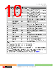
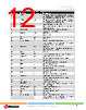
12 / 73 page  WINCS02IC and WINCS02 Family Device Overview Data Sheet © 2024-2025 Microchip Technology Inc. and its subsidiaries DS70005577B - 12 Table 2-2. WINCS02 Module Pinout Table (continued) Pin Number Pin Name Pin Type Pin Description 2 I2C_SCL I I2C clock connected to Trust&GO device. Recommended to connect external pull-up resistor of 1.2K on the host board for WINCS02PC and WINCS02UC devices. 3 I2C_SDA I/O I2C data connected to Trust&GO device. Recommended to connect external pull-up resistor of 1.2K on the host board for WINCS02PC and WINCS02UC devices. 4 MCLR I Master Clear Reset Input (Active low) 5 PTA_WLAN_ACTIVE O PTA interface, WLAN Active indication output to Bluetooth® Coexistence device 6 PTA_BT_PRIO I PTA interface, Bluetooth Coexistence device priority indication input to WINCS02 7 Reserved I/O Reserved pin Do not connect. 8 NC — No connection 9 GND P Ground 10 DFU_RX/STRAP1 I Device Firmware Update, receive signal Host interface configuration, Strapping1 pin. For more details on exact configuration, refer to Table 2-3. 11 Reserved(5) — Reserved pin Connect to an I/O pin (tri-stated) of a host device or to an external switch for future use. 12 GND P Ground 13 INTOUT O Interrupt request (Active low) from the Wi-Fi® module 14 UART1_TX(4) O Used for external antenna calibration Connect this signal to a test point or a pin header. 15 SDI1 I SPI1, Serial Data In Connect to Serial Data Out of the host device 16 CS1 I SPI1, Chip Select (Active low) Connect to the Chip Select of host device 17 SDO1 O SPI1, Serial Data Out Connect to the Serial Data In of the host device 18 SCK1 I SPI1, Serial Clock Connect to the Serial Clock of the host device 19 UART1_RX(4) I Used for external antenna calibration Connect this signal to a test point or a pin header. 20 VDD P VDD power supply (3.0-3.6V) 21 RTCC_OSC_IN/ PTA_BT_ACTIVE(1)(3) I 32.768 KHz RTCC Oscillator input PTA interface, Bluetooth Coexistence device active indication input to WINCS02 22 RTCC_OSC_OUT(3) O 32.768 KHz RTCC Oscillator output 23 VDDIO P I/O power supply (3.0-3.3V) 24 TP P PMU Output Test point: 1.5V(2) 25 NC — No connection 26 DFU_TX/STRAP2 O Device Firmware Update, transmit signal I Host interface configuration, Strapping2 pin. For more details on exact configuration, refer to the Table 2-3. |
|
链接网址 |
| ALLDATASHEET是否为您带来帮助? [ DONATE ] |
关于 Alldatasheet | 广告服务 | 联系我们 | 隐私政策 | 数据表链接 | 链接交换 | 制造商名单 All Rights Reserved©Alldatasheet.com |
| Russian : Alldatasheetru.com | Korean : Alldatasheet.co.kr | Spanish : Alldatasheet.es | French : Alldatasheet.fr | Italian : Alldatasheetit.com Portuguese : Alldatasheetpt.com | Polish : Alldatasheet.pl | Vietnamese : Alldatasheet.vn Indian : Alldatasheet.in | Mexican : Alldatasheet.com.mx | British : Alldatasheet.co.uk | New Zealand : Alldatasheet.co.nz |
|
Family Site : ic2ic.com |
icmetro.com |
 Chinese ▼
 English
 Chinese
 German
 Japanese
 Russian
 Korean
 Spanish
 French
 Italian
 Portuguese
 Polish
 Vietnamese
 Indian
 Mexican
 British
 New Zealand