|
数据搜索系统,热门电子元器件搜索 |
|
|
数据搜索系统,热门电子元器件搜索 |
|
ANT-2.4-CW-RCL-RPS 数据表(PDF) 16 Page - Microchip Technology |
|
|
|||||||||||||||||||||||||||||
ANT-2.4-CW-RCL-RPS 数据表(HTML) 16 Page - Microchip Technology |
|
|
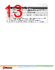
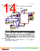
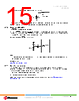
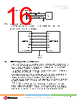
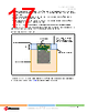
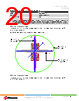
16 / 73 page  WINCS02IC and WINCS02 Family Device Overview Data Sheet © 2024-2025 Microchip Technology Inc. and its subsidiaries DS70005577B - 16 Figure 2-7. Basic Connection Diagram of DFU 0R R12 GND 0R R11 WINCS02 26 4 10 DFU_TX/STRAP2 DFU_RX/STRAP1 M C L R 2.3.4 Interface with Host Microcontroller The WINCS02 Module can be interfaced with the host microcontroller through the SPI. Figure 2-8. WINCS02 Module Host Interface Diagram WINCS02 HOST MCU MCLR SDI1 SDO SDI SDO1 CS CS1 SCK SCK1 User Button (Optional) INTOUT Pin11 Reserved I/O Tristate I/O GPIO INTIN 2.4 WINCS02 Module Placement Guidelines • For any Wi-Fi® product, the antenna placement affects the performance of the whole system. The antenna requires free space to radiate RF signals, and it must not be surrounded by the ground plane. Thus, for the best PCB antenna performance, it is recommended that the WINCS02PC/E Module is placed at the edge of the host board. • The WINCS02PC/WINCS02PE Module ground outline edge must be aligned with the edge of the host board ground plane as shown in the following figure. • A low-impedance ground plane for the WINCS02 Module ensures the best radio performance (best range and lowest noise). The ground plane can be extended beyond the minimum recommendation as required for the host board EMC and noise reduction. • For the best performance, keep metal structures and components (such as mechanical spacers, bump-on and so on) at least 31.75 mm away from the PCB trace antenna as illustrated in the following figure. • The antenna on the WINCS02 Module must not be placed in direct contact with or in close proximity to plastic casing or objects. Keep a minimum clearance of 10 mm in all directions around the PCB antenna as shown in the following figure. Keeping metallic and plastic objects close to the antenna can detune the antenna and reduce the performance of the device. |
|
链接网址 |
| ALLDATASHEET是否为您带来帮助? [ DONATE ] |
关于 Alldatasheet | 广告服务 | 联系我们 | 隐私政策 | 数据表链接 | 链接交换 | 制造商名单 All Rights Reserved©Alldatasheet.com |
| Russian : Alldatasheetru.com | Korean : Alldatasheet.co.kr | Spanish : Alldatasheet.es | French : Alldatasheet.fr | Italian : Alldatasheetit.com Portuguese : Alldatasheetpt.com | Polish : Alldatasheet.pl | Vietnamese : Alldatasheet.vn Indian : Alldatasheet.in | Mexican : Alldatasheet.com.mx | British : Alldatasheet.co.uk | New Zealand : Alldatasheet.co.nz |
|
Family Site : ic2ic.com |
icmetro.com |
 Chinese ▼
 English
 Chinese
 German
 Japanese
 Russian
 Korean
 Spanish
 French
 Italian
 Portuguese
 Polish
 Vietnamese
 Indian
 Mexican
 British
 New Zealand