|
数据搜索系统,热门电子元器件搜索 |
|
|
数据搜索系统,热门电子元器件搜索 |
|
ADRF6820ACPZ-R7 数据表(PDF) 21 Page - Analog Devices |
|
|
|||||||||||||||||||||||||||||
ADRF6820ACPZ-R7 数据表(HTML) 21 Page - Analog Devices |
|
|
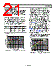
21 / 45 page  Data Sheet ADRF6820 Rev. C | Page 21 of 45 BANDWIDTH SELECT MODES The ADRF6820 offers four bandwidth select modes, as specified in Table 15. The bandwidth select modes include either high gain and low bandwidth or low gain and high bandwidth. The selection of the resistance and capacitance in the mixer load determines the IF gain and bandwidth. Use Register 0x34, Bits[9:8] to select one of the four modes. The high gain modes, BWSEL0 and BWSEL1, have equivalent performance in terms of gain, noise figure, and linearity. Similarly, the low gain modes, BWSEL2 and BWSEL3, share the same performance specifications. However, the factor that distinguishes the different modes is the IF bandwidth. Figure 39 to Figure 42 show the voltage gain, pass-band flatness, and 1 dB bandwidth of the bandwidth modes for the various LO frequencies. Table 15 summarizes the results of Figure 39 to Figure 42. Table 15. Mixer Gain and Bandwidth Select Modes1 BWSEL (Reg. 0x34[9:8]) Mode Voltage Gain (dB) 1 dB BW (MHz) 3 dB BW (MHz) 00 BWSEL0 +2 240 480 01 BWSEL1 +2 180 340 10 BWSEL2 −3 600 1400 11 BWSEL3 −3 500 900 1 fLO = 2100 MHz, high-side LO injection. LO = 1800 MHz LO = 2100 MHz LO = 2700 MHz –300 –200 –100 0 100 200 300 IF FREQUENCY (MHz) –4.0 –3.5 –3.0 –2.5 –2.0 –1.5 –1.0 –0.5 0 0.5 1.0 1.5 2.0 2.5 3.0 3.5 4.0 Figure 39. Voltage Gain vs. IF Frequency, BWSEL = 0, LO Fixed and RF Swept The LO frequency was set to 1800 MHz, 2100 MHz, and 2700 MHz, and the RF frequency was swept. With this measurement approach, Figure 39 to Figure 42 show the effects of both the RF and IF roll-off. The RF roll-off is determined by the integrated RF balun, and the IF roll-off is set by the bandwidth select mode. The effect of both the RF roll-off and IF roll-off is most evident in the widest bandwidth mode (BWSEL2), as shown in Figure 41. Figure 41 shows the flattest and widest bandwidth when the LO frequency is at 2700 MHz because the RF frequency is farthest from the roll-off of the integrated RF balun. In the fLO = 1800 MHz and fLO = 2100 MHz sweeps, the effect of the RF balun becomes evident, resulting in a narrower 1 dB bandwidth. It is very difficult to accurately measure the voltage gain flatness of the ADRF6820 because the signal generators and spectrum analyzers introduce their own amplitude inaccuracies. Additionally, at higher frequencies, the board traces are not as well matched, resulting in signal reflections. With the amplitude errors/inaccuracies from the signal generators and spectrum analyzers included in the measurement, the gain flatness of the ADRF6820 is approximately 0.3 dB for any 100 MHz bandwidth, or approximately 0.2 dB for any 20 MHz bandwidth. By design, the gain flatness of the ADRF6820 is substantially better than this; however, the measurement approach is the limiting factor, and the result is quoted as such. Figure 39 to Figure 42 show data for both positive and negative IF frequencies; positive IF frequencies represent low-side LO injection, and negative frequencies represent high-side LO injection. –4.0 –3.5 –3.0 –2.5 –2.0 –1.5 –1.0 –0.5 0 0.5 1.0 1.5 2.0 2.5 3.0 3.5 4.0 –300 –200 –100 0 100 200 300 IF FREQUENCY (MHz) LO = 1800MHz LO = 2100MHz LO = 2700MHz Figure 40. Voltage Gain vs. IF Frequency, BWSEL = 1, LO Fixed and RF Swept |
|
链接网址 |
| ALLDATASHEET是否为您带来帮助? [ DONATE ] |
关于 Alldatasheet | 广告服务 | 联系我们 | 隐私政策 | 数据表链接 | 链接交换 | 制造商名单 All Rights Reserved©Alldatasheet.com |
| Russian : Alldatasheetru.com | Korean : Alldatasheet.co.kr | Spanish : Alldatasheet.es | French : Alldatasheet.fr | Italian : Alldatasheetit.com Portuguese : Alldatasheetpt.com | Polish : Alldatasheet.pl | Vietnamese : Alldatasheet.vn Indian : Alldatasheet.in | Mexican : Alldatasheet.com.mx | British : Alldatasheet.co.uk | New Zealand : Alldatasheet.co.nz |
|
Family Site : ic2ic.com |
icmetro.com |
 Chinese ▼
 English
 Chinese
 German
 Japanese
 Russian
 Korean
 Spanish
 French
 Italian
 Portuguese
 Polish
 Vietnamese
 Indian
 Mexican
 British
 New Zealand