|
数据搜索系统,热门电子元器件搜索 |
|
|
数据搜索系统,热门电子元器件搜索 |
|
ADRF6820ACPZ-R7 数据表(PDF) 23 Page - Analog Devices |
|
|
|||||||||||||||||||||||||||||
ADRF6820ACPZ-R7 数据表(HTML) 23 Page - Analog Devices |
|
|
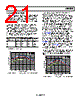
23 / 45 page  Data Sheet ADRF6820 Rev. C | Page 23 of 45 IP3 AND NOISE FIGURE OPTIMIZATION The ADRF6820 can be configured for either improved performance or reduced power consumption. In applications where performance is critical, the ADRF6820 offers IP3 or noise figure optimization. However, if power consumption is the priority, the mixer bias current can be reduced to save on overall power at the expense of degraded performance. Depending on the application specific needs, the ADRF6820 offers configurability that balances performance and power consumption. Adjustments to the mixer bias setting have the most impact on performance and power. For this reason, first adjust the mixer bias. The active mixer core of the ADRF6820 is a linearized transconductor. With increased bias current, the transconductor becomes more linear, resulting in higher IP3. The higher IP3, however, is at the expense of degraded noise figure and increased power consumption. For a 1-bit change of the mixer bias (MIX_BIAS, Register 0x31, Bits[12:10]), the total mixer current increases by 8 mA. Inevitably, there is a limit on how much the bias current can increase before the improvement in linearity no longer justifies the increase in power and noise. The mixer core reaches a point where further increases in bias current do not translate to improved linearity performance. When that point is reached, decrease the bias current to a level where the desired performance is achieved. Depending on the system specifications of the customer, a balance between linearity, noise figure, and power can be attained. 0 5 10 15 0 10 20 25 30 35 40 RDAC 26 28 30 32 34 36 38 Figure 43. IIP3 vs. DEMOD_CDAC and DEMOD_RDAC, MIX_BIAS = 3 at fRF = 900 MHz In addition to bias optimization, the ADRF6820 also has configurable distortion cancellation circuitry. The linearized transconductor input of the ADRF6820 is composed of a main path and a secondary path. Through adjustments of the amplitude and phase of the secondary path, the distortion generated by the main path can be canceled, resulting in improved IP3 performance. The amplitude and phase adjustments are located in the following serial interface bits: DEMOD_RDAC (Register 0x31, Bits[8:5]) and DEMOD_CDAC (Register 0x31, Bits[3:0]). Figure 43 to Figure 46 show the input IP3 and noise figure sweeps for all DEMOD_RDAC, DEMOD_CDAC, and MIX_BIAS combinations. The input IP3 vs. DEMOD_RDAC and DEMOD_CDAC figures show both a surface and a contour plot in one figure. The contour plot is located directly underneath the surface plot. The best approach for reading the figures is to locate the peaks on the surface plot, which indicate maximum input IP3, and to follow the same color pattern to the contour plot to determine the optimized DEMOD_RDAC and DEMOD_CDAC values. The overall shape of the input IP3 plot does not vary with the MIX_BIAS setting; therefore, only MIX_BIAS = 011 is displayed. Table 16 shows the recommended MIX_BIAS, DEMOD_RDAC, and DEMOD_CDAC settings for various RF frequencies. Use Table 16 and Figure 43 to Figure 46 as guides only; do not interpret them in the absolute sense because every application and input signal varies. 0 5 10 15 0 5 10 15 20 25 30 35 40 CDAC RDAC 24 26 28 30 32 34 36 38 Figure 44. IIP3 vs. DEMOD_CDAC and DEMOD_RDAC, MIX_BIAS = 2 at fRF = 1900 MHz |
|
链接网址 |
| ALLDATASHEET是否为您带来帮助? [ DONATE ] |
关于 Alldatasheet | 广告服务 | 联系我们 | 隐私政策 | 数据表链接 | 链接交换 | 制造商名单 All Rights Reserved©Alldatasheet.com |
| Russian : Alldatasheetru.com | Korean : Alldatasheet.co.kr | Spanish : Alldatasheet.es | French : Alldatasheet.fr | Italian : Alldatasheetit.com Portuguese : Alldatasheetpt.com | Polish : Alldatasheet.pl | Vietnamese : Alldatasheet.vn Indian : Alldatasheet.in | Mexican : Alldatasheet.com.mx | British : Alldatasheet.co.uk | New Zealand : Alldatasheet.co.nz |
|
Family Site : ic2ic.com |
icmetro.com |
 Chinese ▼
 English
 Chinese
 German
 Japanese
 Russian
 Korean
 Spanish
 French
 Italian
 Portuguese
 Polish
 Vietnamese
 Indian
 Mexican
 British
 New Zealand