|
数据搜索系统,热门电子元器件搜索 |
|
|
数据搜索系统,热门电子元器件搜索 |
|
R5F104FCAFP 数据表(PDF) 79 Page - Renesas Technology Corp |
|
|
|||||||||||||||||||||||||||||
R5F104FCAFP 数据表(HTML) 79 Page - Renesas Technology Corp |
|
|
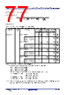
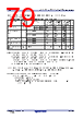
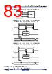
79 / 207 page  RL78/G13 2. ELECTRICAL SPECIFICATIONS (TA = –40 to +85°C) R01DS0131EJ0350 Rev.3.50 79 of 200 Jun 30, 2020 (2) During communication at same potential (CSI mode) (master mode, SCKp... internal clock output, corresponding CSI00 only) (TA = –40 to +85°C, 2.7 V ≤ EVDD0 = EVDD1 ≤ VDD ≤ 5.5 V, VSS = EVSS0 = EVSS1 = 0 V) Parameter Symbol Conditions HS (high-speed main) Mode LS (low-speed main) Mode LV (low-voltage main) Mode Unit MIN. MAX. MIN. MAX. MIN. MAX. SCKp cycle time tKCY1 tKCY1 ≥ 2/fCLK 4.0 V ≤ EVDD0 ≤ 5.5 V 62.5 250 500 ns 2.7 V ≤ EVDD0 ≤ 5.5 V 83.3 250 500 ns SCKp high-/low-level width tKH1, tKL1 4.0 V ≤ EVDD0 ≤ 5.5 V tKCY1/2 – 7 tKCY1/2 – 50 tKCY1/2 – 50 ns 2.7 V ≤ EVDD0 ≤ 5.5 V tKCY1/2 – 10 tKCY1/2 – 50 tKCY1/2 – 50 ns SIp setup time (to SCKp ↑) Note 1 tSIK1 4.0 V ≤ EVDD0 ≤ 5.5 V 23 110 110 ns 2.7 V ≤ EVDD0 ≤ 5.5 V 33 110 110 ns SIp hold time (from SCKp ↑) Note 2 tKSI1 2.7 V ≤ EVDD0 ≤ 5.5 V 10 10 10 ns Delay time from SCKp ↓ to SOp output Note 3 tKSO1 C = 20 pF Note 4 10 10 10 ns Notes 1. When DAPmn = 0 and CKPmn = 0, or DAPmn = 1 and CKPmn = 1. The SIp setup time becomes “to SCKp ↓” when DAPmn = 0 and CKPmn = 1, or DAPmn = 1 and CKPmn = 0. 2. When DAPmn = 0 and CKPmn = 0, or DAPmn = 1 and CKPmn = 1. The SIp hold time becomes “from SCKp ↓” when DAPmn = 0 and CKPmn = 1, or DAPmn = 1 and CKPmn = 0. 3. When DAPmn = 0 and CKPmn = 0, or DAPmn = 1 and CKPmn = 1. The delay time to SOp output becomes “from SCKp ↑” when DAPmn = 0 and CKPmn = 1, or DAPmn = 1 and CKPmn = 0. 4. C is the load capacitance of the SCKp and SOp output lines. Caution Select the normal input buffer for the SIp pin and the normal output mode for the SOp pin and SCKp pin by using port input mode register g (PIMg) and port output mode register g (POMg). Remarks 1. This value is valid only when CSI00’s peripheral I/O redirect function is not used. 2. p: CSI number (p = 00), m: Unit number (m = 0), n: Channel number (n = 0), g: PIM and POM numbers (g = 1) 3. fMCK: Serial array unit operation clock frequency (Operation clock to be set by the CKSmn bit of serial mode register mn (SMRmn). m: Unit number, n: Channel number (mn = 00)) |
|
链接网址 |
| ALLDATASHEET是否为您带来帮助? [ DONATE ] |
关于 Alldatasheet | 广告服务 | 联系我们 | 隐私政策 | 数据表链接 | 链接交换 | 制造商名单 All Rights Reserved©Alldatasheet.com |
| Russian : Alldatasheetru.com | Korean : Alldatasheet.co.kr | Spanish : Alldatasheet.es | French : Alldatasheet.fr | Italian : Alldatasheetit.com Portuguese : Alldatasheetpt.com | Polish : Alldatasheet.pl | Vietnamese : Alldatasheet.vn Indian : Alldatasheet.in | Mexican : Alldatasheet.com.mx | British : Alldatasheet.co.uk | New Zealand : Alldatasheet.co.nz |
|
Family Site : ic2ic.com |
icmetro.com |
 Chinese ▼
 English
 Chinese
 German
 Japanese
 Russian
 Korean
 Spanish
 French
 Italian
 Portuguese
 Polish
 Vietnamese
 Indian
 Mexican
 British
 New Zealand