|
数据搜索系统,热门电子元器件搜索 |
|
|
数据搜索系统,热门电子元器件搜索 |
|
AS3953 数据表(PDF) 9 Page - ams AG |
|
|
|||||||||||||||||||||||||||||
AS3953 数据表(HTML) 9 Page - ams AG |
|
|
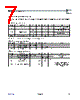
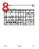
9 / 42 page  www.ams.com Revision 1.0 9 - 42 AS3953 Datasheet - D e t a il e d D es c r i pt io n 7 Detailed Description Figure 3. System Block Diagram 7.1 Circuit The AS3953 is composed of ISO 14443A PICC Analog Front-end (PICC AFE), the ISO 14443A PICC Logic (PICC Logic), EEPROM, SPI Interface, Level Shifters and Power Supply Manager Block (Power Manager). The PICC AFE is connected to an external tag coil, which forms together with integrated resonant capacitor an LC tank with a resonance at the external electromagnetic field frequency of 13.56 MHz. The PICC AFE has a built in rectifier and regulators. Output of internal regulator is called VP_INT. It is used to supply the PICC AFE and usually also the LOGIC and EEPROM (through Power Supply Manager). Output of external regulator VP_REG is available on a pin to supply some external circuitry. Power Manager is controlling power supply of Logic and EEPROM. The two blocks can be supplied either from VP_INT or from VP_SPI (SPI power supply). In order to save current on VP_SPI, VP_INT is used as power supply whenever it is available. VP_SPI is only used when some activity is started over the SPI and the VP_REG is too low to be used as a power supply. The PICC Logic is responsible for PICC-to-PCD communication up to the Level-4 (block transmission) of ISO 14443A. This means that anti- collision and other low-level functionality are implemented there. The SPI Interface logic contains a 32 byte FIFO for block transmission data which is exchanged on Level-4 of ISO 14443A communication. It also contains some control and display registers. The EEPROM is used to store the UID, the housekeeping data (configuration and control bits) and user data. It can be accessed from both sides (RFID and SPI). 7.2 PICC AFE Figure 4 depicts main PICC AFE building blocks. The PICC AFE is connected to external tag coil, which together with the integrated resonant capacitor forms an LC tank with resonance at external electromagnetic field frequency (13.56 MHz). Figure 4 depicts the main PICC AFE building blocks. Rectifier: Extracts DC power supply from AC voltage induced on coil terminals. Limiter: Limits the maximum voltage on coil terminals to protect PICC AFE from destruction. At voltages that exceed limiter voltage it starts to absorb current (acts as some sort of shunt regulator). Modulator Switch: Is used for communication PICC-to-PCD. When switched on, it will draw current from coil terminals. This mechanism is called load modulation. Variation of current in the modulator switch (ON and OFF state) is seen as modulation by the PCD. Demodulator: Is used for communication PICC-to-PCD. It detects AM modulation of the PCD magnetic field. The demodulator is designed to accept modulation according to ISO 14443A; all standard bit rates from 106 kb/s to 848 kb/s are supported. The modulation for bit rate 106 kb/s is 100%, whereas for other bit rates it may be less. ISO 14443A Reader AS3953 Microcontroller SPI |
|
链接网址 |
| ALLDATASHEET是否为您带来帮助? [ DONATE ] |
关于 Alldatasheet | 广告服务 | 联系我们 | 隐私政策 | 数据表链接 | 链接交换 | 制造商名单 All Rights Reserved©Alldatasheet.com |
| Russian : Alldatasheetru.com | Korean : Alldatasheet.co.kr | Spanish : Alldatasheet.es | French : Alldatasheet.fr | Italian : Alldatasheetit.com Portuguese : Alldatasheetpt.com | Polish : Alldatasheet.pl | Vietnamese : Alldatasheet.vn Indian : Alldatasheet.in | Mexican : Alldatasheet.com.mx | British : Alldatasheet.co.uk | New Zealand : Alldatasheet.co.nz |
|
Family Site : ic2ic.com |
icmetro.com |
 Chinese ▼
 English
 Chinese
 German
 Japanese
 Russian
 Korean
 Spanish
 French
 Italian
 Portuguese
 Polish
 Vietnamese
 Indian
 Mexican
 British
 New Zealand