|
数据搜索系统,热门电子元器件搜索 |
|
|
数据搜索系统,热门电子元器件搜索 |
|
AS3953 数据表(PDF) 22 Page - ams AG |
|
|
|||||||||||||||||||||||||||||
AS3953 数据表(HTML) 22 Page - ams AG |
|
|
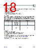
22 / 42 page  www.ams.com Revision 1.0 22 - 42 AS3953 Datasheet - A pp l ic a t io n I n f or m a t i on 8 Application Information 8.1 SPI Interface Communication between the AS3953 and controller is done through a 4-wire Serial Peripheral Interface (SPI) and additional interrupt signal. The AS3953 is an SPI slave device; it requests controller attention by sending an interrupt (IRQ pin). While signal /SS is high the SPI interface is in reset, while it is low the SPI interface is enabled. It is recommended to keep signal /SS high whenever the SPI interface is not in use. MOSI is sampled at the falling edge of SCLK. All communication is done in blocks of 8 bits (bytes). First three bits of first byte transmitted after high to low transition of /SS define SPI operation mode. MSB bit is always transmitted first (valid for address and data). Read and Write modes support address auto incrementing, which means that in case after the address and first data byte some additional data bytes are sent (read), they are written to (read from) addresses incremented by ‘1’. SPI interface supports the following modes: Read and write of the SPI Interface internal registers Read and write of the EEPROM Read and write of the FIFO Sending direct commands Please note that the only SPI operations, which are allowed when logic and EEPROM are supplied from VP_SPI, are reading and writing of EEPROM and registers (see also Power Manager on page 11). MISO output is usually in tristate, it is only driven when output data is available. Due to this the MOSI and the MISO can be externally shorted to create a bidirectional signal. During the time the MISO output is in tristate, it is possible to switch on a 10 k Ω pull-down by activating option bits miso_pd1 and miso_pd2 in IO Configuration Register. Table 7. SPI and Interrupt Signals Name Signal Signal Level Description /SS Digital input with pull-up CMOS SPI enable (active low) MOSI Digital input CMOS Serial data input MISO Digital output with tristate CMOS Serial data output SCLK Digital input CMOS Clock for serial communication IRQ Digital output CMOS Interrupt output pin Table 8. SPI Modes MODE MODE Pattern (communication bits) MODE Related Data MODE Trailer M2 M1 M0 C4 C3 C2 C1 C0 Register Write 0 0 0 A4 A3 A2 A1 A0 Data byte (or more bytes in case of auto incrementing) Register Read 0 0 1 A4 A3 A2 A1 A0 Data byte (or more bytes in case of auto incrementing) EEPROM Write 0 1 0 0000 0 Word Address byte 4 bytes of word data EEPROM Read 0 1 1 1111 1 Word Address byte 4 bytes of word data (or multiple words in case of auto incrementing FIFO Load 100 0000 0 One or more bytes of FIFO data FIFO Read 101 1111 1 One or more bytes of FIFO data COMMAND Mode 1 1 C5 C4 C3 C2 C1 C0 |
|
链接网址 |
| ALLDATASHEET是否为您带来帮助? [ DONATE ] |
关于 Alldatasheet | 广告服务 | 联系我们 | 隐私政策 | 数据表链接 | 链接交换 | 制造商名单 All Rights Reserved©Alldatasheet.com |
| Russian : Alldatasheetru.com | Korean : Alldatasheet.co.kr | Spanish : Alldatasheet.es | French : Alldatasheet.fr | Italian : Alldatasheetit.com Portuguese : Alldatasheetpt.com | Polish : Alldatasheet.pl | Vietnamese : Alldatasheet.vn Indian : Alldatasheet.in | Mexican : Alldatasheet.com.mx | British : Alldatasheet.co.uk | New Zealand : Alldatasheet.co.nz |
|
Family Site : ic2ic.com |
icmetro.com |
 Chinese ▼
 English
 Chinese
 German
 Japanese
 Russian
 Korean
 Spanish
 French
 Italian
 Portuguese
 Polish
 Vietnamese
 Indian
 Mexican
 British
 New Zealand